This is all quite complicated and so a full page has been dedicated to the subject. Most original 1947-53 "Advance Design"
trucks would have had 16 inch wheels (at 6 inches wide) and 4 ply tyres. The total diameter of an original wheel and tyre
would have been about 686mm This has been estimated in two ways. Firstly the width of the original tyres was 6 inches and
so an estimate of the tyre height for that type of tyre would have been about 5 and 1/5 inches. This gives 16 inches + 5
and 1/5 inches + 5 and 1/5 inches = 27 inches or 685.8mm. Secondly if you look at an extract from the official GM table
for the 3100 (1/2 ton) "Advance Design" truck, the rolling radius is 27 inches which again results in a diameter of 685.8mm.
Here it has been rounded to 686mm The table below shows a rolling radius of 13.5 inches which is 27 inches diameter
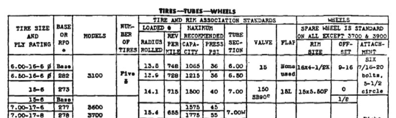
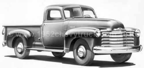
Whitewall tyres were not available prior to 1955. Four ply blackwall tyres were fitted. Original wheels had 6 holes for 6 studs.
A useful site specialising in original truck information is at
http://www.antiquechevytrucks.com/Content/Orginal%20Restoration/advancedesign_main.htm
Background - 1998 -
The 52 truck had been restored in the States in 1998 and I bought it in 2007. It is likely the alloy wheels were fitted in 1998.
When purchased in 2007 the truck had four 15 inch "Pacer" alloy wheels at 7 inches wide and the tyres fitted were Michelin
235/75/R15 radials which gave an overall diameter of 734mm. This diameter is a bit larger than the 686mm size of the original
1952 wheels and tyres. It is 50mm larger in diameter 25mm larger in radius. That is 2 inches larger in diameter and 1 inch
larger in radius. This raises the truck by 1 inch front and back but has little relevance as the springs on the front were
totally different (Mustang II suspension) which lowers the front suspension and the rear axle was different as well. All
of these changes meant the front and rear height would have altered anyway. Therefore the effect of the
slightly larger wheel diameter is not significant factor.
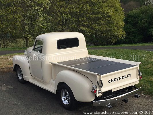
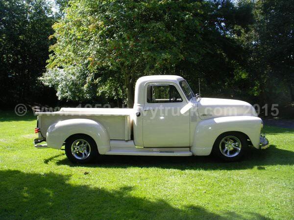
The picture below shows the truck in August 2007 with the 15 inch "Pacer" alloy rims. All tyres are Michelin 235/75/15R.
Background - 2009 -
In 2009 the front tyres (only) were changed to 225/60/R15. These tyres were therefore smaller at 651mm diameter. Indeed the front
wheels were now 82mm smaller in diameter than the back which was still 734mm. This was done to improve handling but it also had
the effect of making the ride poor. In addition, the truck was now very low at the front. It was so low at the front, it was now not
possible to push a trolley jack under the truck without manually lifting the front usually from the bumper bar. The "stance" was
also very aggressive. "Stance" refers to whether the truck is level from front to back, low at the back or low at the front.
Cars and trucks which are low at the back do not look good. Indeed this type of stance looks like the suspension has failed or
become soft as it might in an old vehicle that had not been cared for. Level looks fine but usually higher at the back than
the front i.e. an aggressive attitude or stance looks good (within reason). The stance can be adjusted by using larger wheels
at the back than at the front, or it can be adjusted by increasing or decreasing the strength of springs at the back or the front.
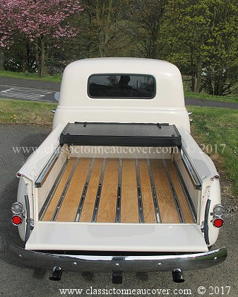
Looking at the original truck at the top of the page, the stance appears to be neutral or level.
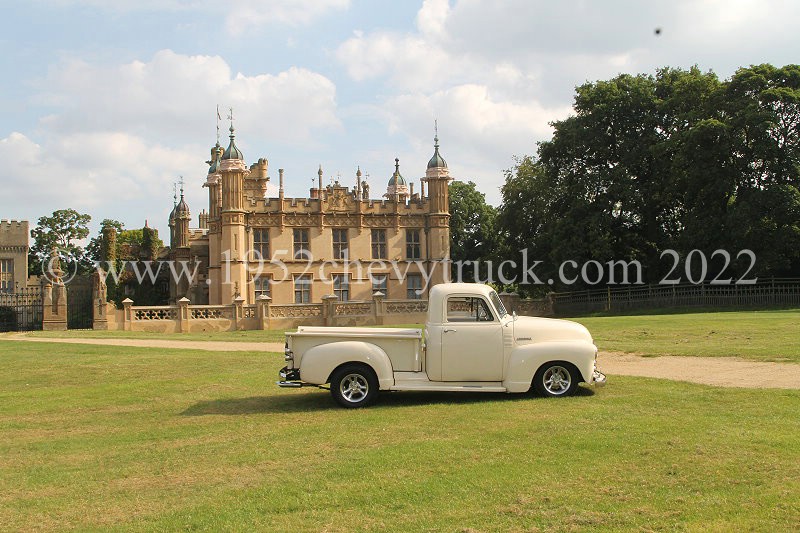
The picture below shows the truck in July 2011 with the 15 inch "Pacer" alloy rims. The front tyres are now 225/60/15R. As you
can see the front tyres are small and the truck is very low at the front. Too small and too low in my opinion.
The new wheels. 2014.
It was decided to buy new wheels for the truck. The original "Pacer" wheels were excellent but were showing signs of age. New
"Pacer" wheels would have been ideal but it was found "Pacer" were no longer in business. After some research it was found the
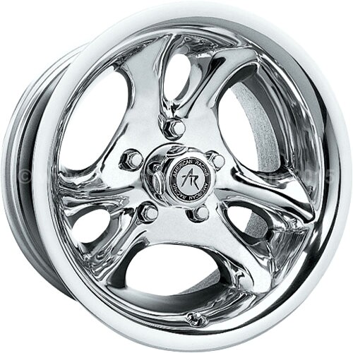
"American Racing Ventura" wheels are the same as the "Pacer" wheels apart from the centre cap and logo. It is possible
"American Racing" may have bought the design at some point since 1998 maybe when "Pacer" ceased trading? New wheels
were purchased but instead of 15 inch by 7 inches wide, the new wheels selected were 15 inches by 8 inches wide.
In addition, instead of having a "zero offset", they have an offset of "-19". More about that later.
The centre caps say American racing. The old Pacer wheels were not sold.
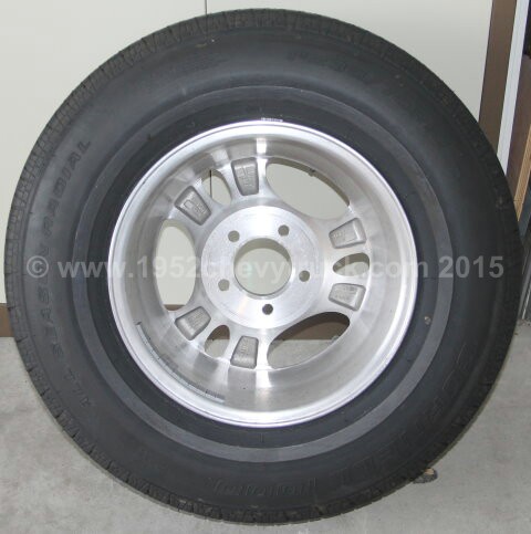
American Racing Polished Wheels
Finding a supplier -
The American Racing wheels were purchased from www.4wheelparts.com This company is not always the cheapest
for parts but they are competitive and are usually close to the cheapest. 4wheelparts do, however, ship internationally
at very competitive rates. If you can find a company who will ship internationally (without going through an expensive
forwarding agent) it is likely there will only be expensive courier options like UPS or FedEx and typically the price of
shipping 4 rims to the UK will be about $750. 4wheelparts tend to use the insured US mail postal service and this is
usually passed on to Parcelforce once it enters the UK. This type of delivery will probably cost only about 25% of the
other options. e.g. If a delivery is to cost $800, the US mail option will be about $200. This makes 4wheelparts the
cheapest way by far to buy rims (and other items) with international shipping from the USA. It is also worth checking
out other products from them as even if they do not have it on their site, they will order an item in from a company
they deal with. Strangely these rims arrived from 4wheelparts using UPS and the shipping costs were no still higher ?? !!
Choosing the right wheels for this truck -
Let us now consider offset distances. The original "Pacer" alloy wheels has zero offset and the backspace was 3.75 inches.
That meant the plate that is offered up to the hub or stub axle is in the centre of the wheel. (See theory notes below
and the rim cross sectional diagram). These original alloy 15 inch wheels at 7 inches wide gave the truck a fairly narrow
track at the front. This was mainly a result of the Mustang II suspension which does tend to have a narrow track (e.g.
compared to trucks which use a "Camaro" front "clip" suspension.) By using a new "American Racing" 15 inch wheel at 8
inches wide with an offset of -19 and backspace of 3.75 inches a wider track is achieved. To explain what this
means consider the new "American Racing" wheel's backplate to be in the same position as with the "Pacer" wheel's
backplate, however, since the new wheel is an inch wider at 8 inches, all of that extra inch is pushed outwards. The
wheel has a deeper "dish" and since more of the wheel (an inch) is outboard, the track is widened by 2 inches (one inch
per wheel). It would be difficult to widen the track on an already installed suspension and so by using a wider wheel
with negative offset and deeper dish pushing the wheel outwards, a wider track is achieved. A wider track both improves
handling and looks better. Wheels which look inboard and do not approach the inside edge of the wheel arch do not look
good and they look like classic older vehicles. Modern cars and trucks have the wheels right up the edge or the arches.
If the aim is to own cool looking hotrod a wider track looks much better.
Wheel offset distances. The theory -
The offset and back spacing (called "Rear Spacing" in diagram below) are important. This details the distance from your
hub (stub axle) to the back face of the rim where the studs go through. (Note. Back spacing is measured in mm or inches) A zero
offset means the face is in the centre of the width of the wheel. If the offset is positive, that means the back spacing is large.
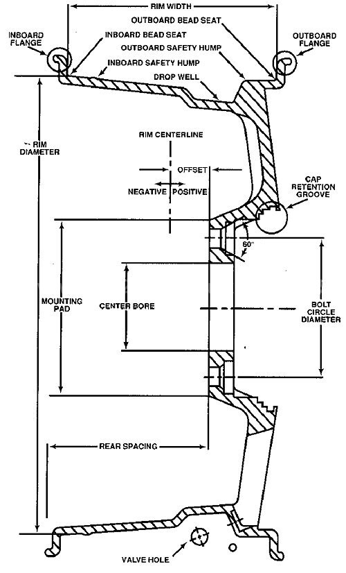
With a positive offset the outside of the wheels would only have only a slight “dish” and most of the width of the wheel would
be inboard. If the offset is negative, this means that the back spacing is small, the wheels have a deep dish and most of the
wheel is outboard providing a wider track. It is important to check the clearance when wider rims and tyres are to be fitted.
Make sure the wheels do not foul the inside of the inner or outer wings or quarter panels. This check must be done while
turning and breaking (as the suspension dips down while breaking). Check the steering from lock to lock. If there is a problem,
the tyre will catch the wheel arch. As a final test try slowly driving up a curb while turning. This compresses the suspension
and again the tyre should not catch the wheel arch.
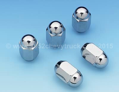
Attractive wheel nuts -
It is worth mentioning the nuts which hold the American Racing wheels onto the truck. Attractive nuts from "Mr Gasket" were
chosen. These are available from Summit Racing manufacturers part number - 1440 and Summit part number - MRG-1440
Price about $50.00 for 4 sets. i.e. 20 nuts. When fitting these wheel nuts a thin walled socket is required so that it sinks into
the holes and gets a good grip on the nuts. Make sure you order the correct size of nuts for the studs used on your vehicle.
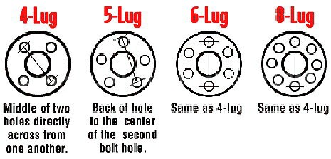
Lug sizes vary with manufacturer and there can be different lug separations even within a manufacturer. For example - the 1952
Chevy truck uses a 5-lug Chevy lug pattern which is 4.75 inches. See below for how that is measured.
Choosing the right tyre -
There are many factors which affect tyre choice. They are listed below.
1. Speed rating.
2. Load rating
3. Dry performance
4. Wet performance
5. Low road noise
6. Comfort - good ride.
7. Appearance.
8. Cost.
9. Tyre reviews
10. Availability.
In case you are wondering why "Tyre Life" has not been included in the list above, when running a classic vehicle it is not usually
an issue. Classic cars and trucks do not tend to do many miles in a year. Indeed classic car insurance usually has restricted mileage.
It is true one of the aims of this project it to produce a vehicle capable of long distances at high speed but that will only be
occasionally and in any event, the cost of buying new tyres more frequently is not as important and performance and appearance.
Cornell 1000
The tyre chosen after much research was the Cornell 1000 from Pep Boys in the States. This tyre is manufactures by
"Cooper Tires" for Pep Boys. From their web site - Cornell 1000. Price - About $300 for 4 tyres. 40.000 miles warranty.
"Cooper Tire founded in 1914 by Ira J. Cooper. Cooper is the 9th largest global tire manufacturer and 4th largest in the U.S.A.
Cooper Tire's focus is on the replacement market, offering value, quality products and exceptional service to our customers.
Cooper Tire manufactures a wide range of passenger, light truck and radial medium truck tires."
Specifications
Tire Size - 235/75 R15
Speed Rating - S
Load Index - 105
Tyre Class - All seasons.
Reviews
There are 75 reviews on the Pep Boys web site and the average rating is 4.5 starts out of 5.
The rating for the areas of most importance to this project are -
Noise Level 4.4 out of 5 (this is important)
Dry traction 4.3 out of 5 (good. Also truck will not be taken out often in the wet).
Handling cornering stability 4.4 out of 5.
Ride / Comfort 4.4 out of 5 (very important).
Why is this Cornell 1000 tyre special?
There are a number of less important parameters in the reviews and many comments but Pep Boys miss out a parameter
which for this project is very important - "Appearance" This is where the Cornell 1000 wins against just about every other
tire type available. It has an attractive tread pattern, one side has a narrow whitewall (which is not needed but that
side is attractive) but most importantly, the other side has an almost completely smooth tyre wall with very little
writing. This is what makes this type very special for classic cars and trucks.
Buying this tyre is difficult if you don't live in the USA as Pep Boys do not ship outside of the States. I was in the
States at the time and I took the tyres to my shipping agent in Pomona California. They came to the UK in a container
with my new transmission and a set of spare doors. Otherwise it would be necessary to use one of those companies
who will buy goods for you and ship them but they are expensive. Also they may not have a "by Sea" option.
When the tyres arrived in the UK it was decided to put black tyre paint on the thin whitewall. Clearly the idea was to
put the whitewall on the inside and have the smooth black tyre pointing outwards. It is not good to see a whitewall
when looking under the vehicle even if it is on the inside. "Car Plan" "Tetrion" black tyre paint was used and is
very good. It is widely available from many suppliers online. Also note - since whitewall tyres were not
available for Chevy trucks until 1955 I decided to use blackwall tyres.
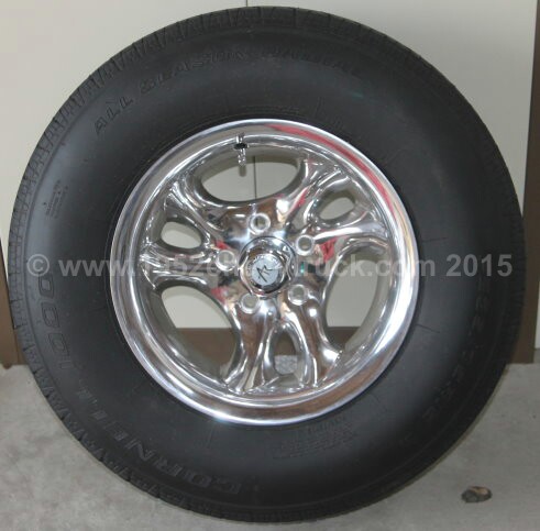
The new wheels and Cornell 1000 tyres are shown below. On the left notice the very smooth tyre wall. On the right
notice the backed out narrow whitewall. As soon as they are put back on the truck a picture will be added here.
Update 2019
It was decided in 2019 after the new TCI ifs was fitted, to change the tyres as one of the measures to lower the truck.
The ideal tyre to purchase as far as appearance is concerned would have been another set of Cornell 100 tyres, this
time using 225/60 R15s. This lowered the truck by 2.4 inches or 61mm. Since I am in the UK and not the USA, buying
Cornell 1000 tyres is not as easy and so "235/60R15 98S TL Nankang Rollnex Cross Sport SP9" SUV tyres were fitted.
Sidewall looked OK but not as good as Cornell.
Why keep the old "Pacer" wheels?
The old wheels and tyres are fitted to the truck through the winter, or when the truck is undergoing restoration work
The new American Racing wheels with Cornell tyres are fitted in the spring for the show season or any other interesting
events. Keeping a set of wheels and tyres "for best" is a good idea. It also means the good wheels and tyres can be
stored in ideal conditions through the winter. They are not standing under load conditions for long periods.
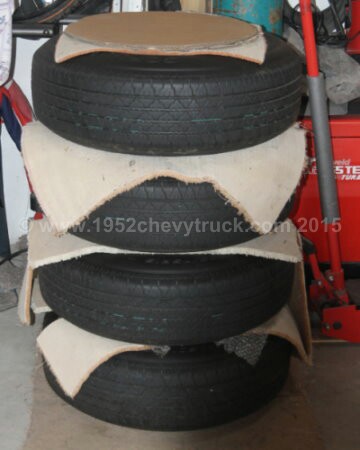
The new American Racing wheels fitted with Cornell 1000 tyres are shown stacked in the garage below.
They are normally stored with a large blanket over the top of them. This was removed for the photograph.
If you want to protect those new tyres from uneven wear, improve the vehicles handing, improve the ride, and breaking
performance, improve the steering, and even the turning circle it is important to check the springs are providing the
required ground clearance and steering clearance. Then make sure the camber, the castor angles and the tracking is all
set up correctly. This is all possible with some inexpensive tools, a bit of knowledge and a resolution to do a
good job yourself. Indeed there are many mechanics who do not understand camber and castor angles.
Wheel (rim) width and tyre size.
Choosing new wheels and tyres for your car is quite a complicated subject. This information may be helpful. Rims have a
number of specifications which need to be checked out - lug spacing, diameter, width and offset / back spacing. Tyre
data to check out - tyre width, tyre profile, rim size, performance and load rating. It is also useful to be able to
work out the final rim and tyre dimensions to make sure the tyre size fits the rim of interest and also to check out
the final diameter of rim with tyre fitted. When deciding the diameter and width of the rim, it is important to check
out what tyre will fit that rim and what width and profile (see below) should be chosen for a particular final diameter
and width. This can be checked out using the table at https://tiresize.com/comparison/
Another good site is at www.wheel-size.com
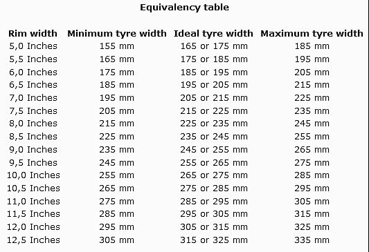
From the table above you can see the relationship between the width of the rim and the ideal tyre width. This shows the
American Racing wheels at 8 inches wide need a tyre width of 225 - 235mm. The Cornel tyres were 235/75 15R.
Tyre information -
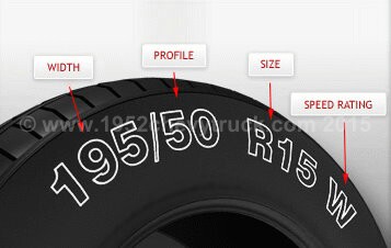
In this example -
195 is the tyre section width in mm (width of the tyre tread.)
50 is the profile or aspect ratio. That is the height of the sidewall divided by the tyre’s width.
(e.g. “high or low profile”)
R denotes the tyres construction. Here - radial.
15 is the rim diameter in inches
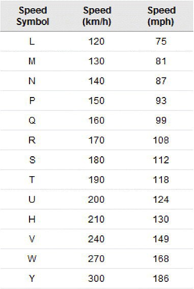
W is the speed rating.
When considering the performance of the tyre, comparisons are needed with other tyres by considering wet
and dry road holding, speed ratings, ride, noise and handling. It is usually best to consider the profile
and width of the tyre to achieve a good compromise between ride, comfort and handling. High profile tyres
are usually best for a comfortable ride. Low profile tyres are best for good handling. As a rough guide,
65 and above tends to offer the best ride and 60 and below offer the best handling. Noise is a product of
the tread pattern and here it is important to research the manufacturer’s data and tyre reviews online.
Indeed, all aspects of a tyre’s performance are best researched online using tyre review web sites.
Finally be sure to check the max. load of the tyre to suit your vehicle. It may be sufficient to see
“car tyres”, “van tyres” or "SUV / light truck tyres" but the dealers notes online will include information.
There is also a load rating stamped on the tyre’s sidewall.
Note- when changing either the rims or the tyres (e.g. snow tyres) from your vehicle's original specification
your insurance company should be informed.