Advanced Engine Transmission Cooling Package
Introduction
When cooling is mentioned most people think “radiators” and whilst radiators are covered in detail here, there is a great
deal more to consider in a comprehensive cooling package. Also covered is the fan, shroud and flaps, ventilation,
water pump, oil pans, heater, hose routing, temperature control and monitoring, building a moulded top and
bottom hose and all of the considerations and equipment for keeping both the engine and transmission cool.
Before looking at the 2019-20 upgrade, let's first look at some previous measures.
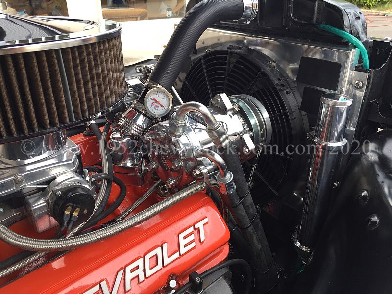
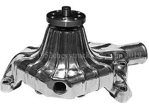
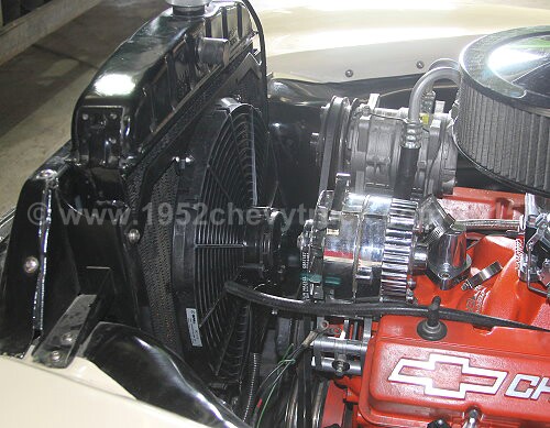
1. In 2015 a new water pump was fitted. The water pump is an aluminium finned short SBC water pump from
“Mooneyes Speed Equipment” USA. Part number WAS6917. The pump now costs $155 (2019). Finned aluminium
provides a small amount of additional cooling due to the fins and aluminium is a better conductor
of heat than steel. The pump is in the airflow as it is right behind the radiator fan.
Update June 2020. Mooneyes have discontinued this pump but it is actually manufactured by
"Racing Power Company" (RPC) and is available from them directly on the RPC Website for $126.95.
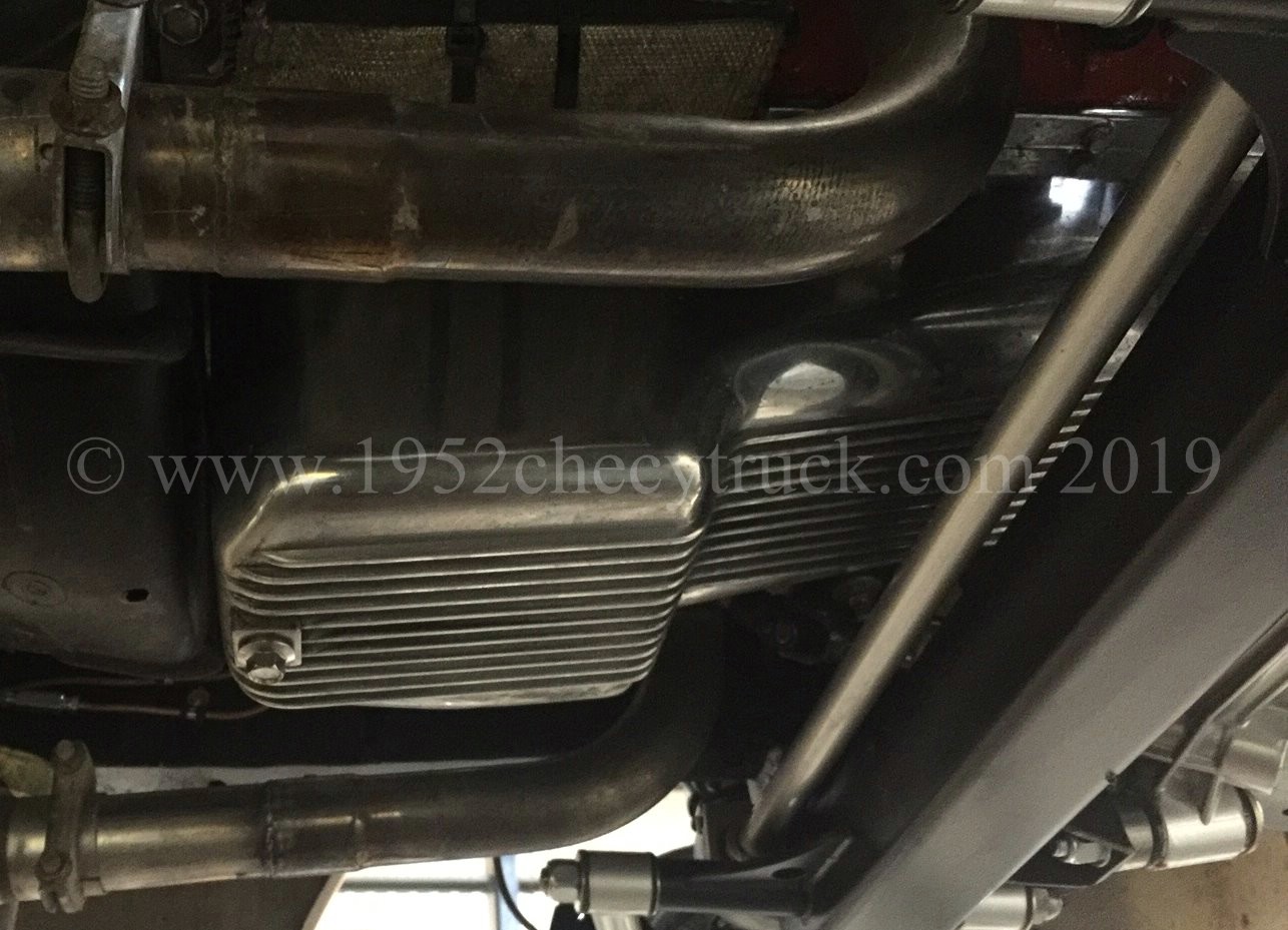
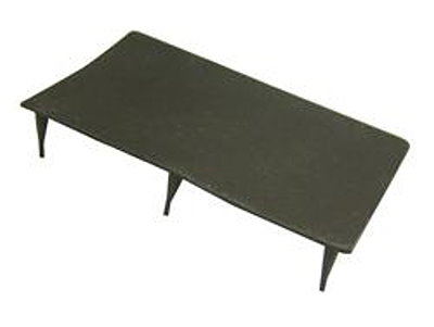
2. In 2015 a "Hughes" finned aluminium deep engine sump pan was fitted.
Finned aluminium provides additional cooling due to the fins. It helps to cool the oil which is then
pumped around the engine. Also aluminium is a better conductor of heat than steel.
The finned sump pan is in the airflow below the truck. Some people also fit finned aluminium rocker covers.
They will also assist cooling, however, this may be at the expense of appearance.
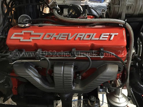
My preference is for the "Chevrolet" rocker covers from GM Racing.
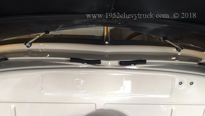
3. This hood ventilation mod was done in May 2017. Some truck owners may put louvers into the hood but that is a step to
far for me as it affects the original appearance too much, however, there is something you can do.
Straight after driving, if you lift the hood are you greeted with a face full of hot air? Cooling the engine with a fan is all
very well but the hot air needs to go somewhere. Cutting and removing some of the rubber sponge roll at the rear of
the hood lets hot air escape. It may be a small mod but it does help and it does work.
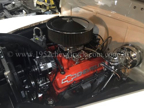
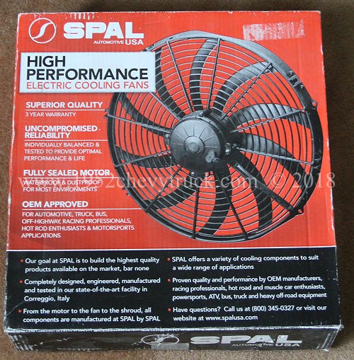
4. Electric fan replacing propeller fan. In may 2007 the old propeller type fan was removed and a temperature
controlled electric fan fitted. In May 2015 the electric fan was replaced with a high performance "Spal" fan.
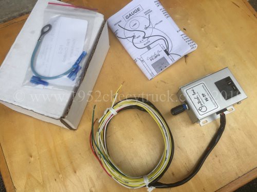
Also in 2015 the fixed temperature control was changed to the excellent adjustable Centech Inc. FC-2P
electronic fan controller (available from Speedway Motors).
With this controller, the temperature at which the fan comes on can be controlled from inside the cab.
Why is it best to fit an electric fan?.
Modern electric fans only come on when they are needed. Most of the time they are off and there is no fan noise.
Fixed propeller fans reduce horsepower, increase fuel consumption and cool the car when it does not need cooling
which in turn delays the heater from heating the cab. Fixed fans run slow at slow speeds when the fan needs to
be effective and fast at high speeds when the fan does not need to be turning. New cars use electric fans for
all of these valid good reasons. As shown elsewhere on this site, fan manufacturers quote the maximum cfm
(cubic feet per minute) which is the amount of air a fan can move through itself. The absolute cfm rating is not
the complete story. As soon as a fan is bolted to a radiator or a shroud, the cfm count goes down. In tests
it has been shown that Spal fans when bolted up, have a lower decrease in cfm flow rate than most other
fans on the market. Also curved fan blades tend to be quieter than straight fan blades. Fans work best
on a shroud and that is dealt with below as part of this new 2019 cooling upgrade.
Make sure your electrical system has been upgraded to deal with the high currents an electric fan can draw,
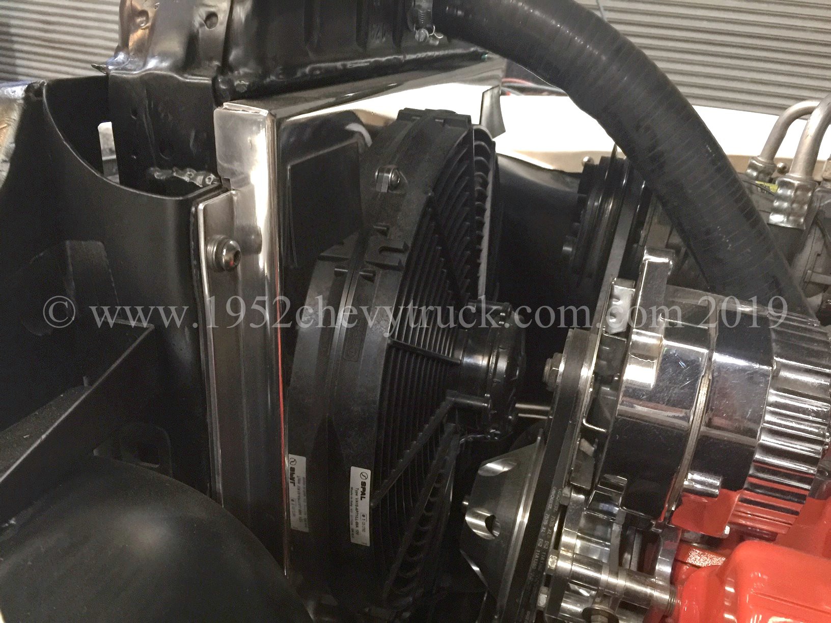
especially the transient switch-on currents. The 16" Spal fan in this truck is only 3.5" thick and since
there can be clearance problems between the fan and the pulley, choosing a thin fan is important.
Note, see below, the part of the fan which lines up with the pulley will be much less than 3.5".
Pull or push fans?
This often has to be decided by clearance issues rather than the science. A V8 is shorter than a straight 6
therefore an original truck may not have the space for a pull fan. There should be no such clearance issues
with a V8 modified truck. In my truck there was room for a fan and shroud. The clearance between the fan
with shroud fitted and the engine pulley is about 13mm (1/2"). A fan should be mounted as high as possible
on a radiator and so the fan motor, which sticks out the most, does not line up with the engine pulley.
Whilst the fan may be 3.5" thick max. the part of the fan which lines up with the pulley is much thinner.
(This next bit is where my degree in Physics helps but I think it is also common sense.)
Part of the science of “Fluid Dynamics” is that when a fan is behind the radiator, all of the ram air goes
through the radiator and the fan does not upset or block the air flow. Yes it disrupts the air flow after
the radiator but by then the air has extracted the heat and done its job. When the fan is in front of the
radiator, the fan stops some of the air from going through the radiator and upsets the “lamina flow” of
the air creating “turbulence” before the cooler air gets to the radiator. This results in less efficient
heat extraction. That being said, if the heat extraction is “enough” with a push fan, then this may not be
a significant problem. The lack of space for a pull fan (e.g. with a straight 6 fitted) may take precedence.
Preparing for the 2019 cooling package upgrade.
Let's start by considering whether the radiator needs to be changed -
When improved engine cooling is considered, truck owners will usually look at the effect of the radiator first.
Let us therefore consider whether keeping the original copper brass radiator or changing it for an aluminium radiator is worthwhile.
The quick answer is that it is not as big a consideration as many people realise and either option is fine.
There are advantages and disadvantages with both options but both work really well. Here are the arguments.
Advantages and disadvantages of copper brass radiators -
1. Keeping the original copper brass radiator maintains originality, however, there are some very good aluminium
copies which look the same and maintain originality. Some aluminium radiators do not look the same as original
radiators but are a good fit and perform well.
2. Not changing something you already have saves time and money.
3. Original copper brass radiators by definition are a very good fit but some aluminium radiators are also a good fit.
4. Copper brass radiators are more efficient since copper is a better conductor of heat than aluminium. This is important.
5. If you do not already have a copper brass radiator, a new one will be much more expensive than an aluminium radiator.
This is a key point for many buyers as aluminium radiators are much cheaper.
6. A copper brass radiator is much heavier than an aluminium radiator. This can effect fuel consumption and performance
but these effects are likely to be negligible with this type of vehicle.
7. The manufacture of copper brass radiators is a more skills based process and highly professional companies are
usually involved. These same companies may also make very high quality aluminium radiators, however,
there are some very cheap aluminium radiators on the market of dubious quality.
8. If you have a good radiator already and it has performed well and been reliable for a number of years, why change it?
There are many sad stories on forums about brand new radiators which leak either straight away or shortly after fitting.
In other words why change something which already works well?
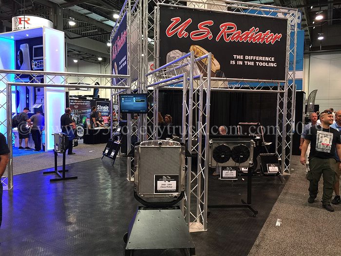
I spoke to the CEO of "US Radiators" at the SEMA show in Las Vegas in Nov. 2018. This is a large long standing US company with
a very good reputation. They are market leaders in radiators design and manufacture. All radiators are made in their factory
in the USA which probably explains why their prices are at the upper end of the scale. You can see in the foreground of the
picture of their stand an aluminium radiator for our trucks with a classic original appearance. They also make an original
appearance copper brass radiator for our trucks. This is what he said -
80% of the radiators we make are copper brass and 20% are aluminium.
If you want to buy an aluminium radiator I will sell you a good one but for most applications
it will not be as good as copper brass. We make radiators from aluminium because there is a
demand and to compete with other companies. Many end users request aluminium but they
usually do not understand the principles or they just need a cheaper product.
The two main advantages of aluminium are -
1. Racing as they are light and power-to-weight ratios are important.
2. They are cheap so good if you are on a budget.
Aluminium is about the same price per pound (weight) as copper brass for me to buy in. An
aluminium radiator uses 6-8 pounds of aluminium whereas a copper brass radiator weighs 28 pounds
so material costs with copper brass are much higher. There are many companies selling aluminium
radiators as they are cheap to make due to low material and manufacturing costs. New cars use
aluminium mainly because they cost less but also because they are lighter which has an effect
on performance and fuel consumption. The main advantage of copper brass is that copper is
more efficient at transferring heat than aluminium for better cooling. Whichever material
you use, good core design can improve cooling efficiency by a further 20%.
I asked about shrouds for the fan and he said a shroud makes a big difference to cooling efficiency as, with
a shroud, the fan pulls the air through all of the radiator.
To summarise his advice, both types do the job but it is worth paying the extra for copper brass if you have the budget
and as long as weight it not a prime consideration as it is more efficient at cooling. Although he did not know it,
he had talked himself out of a sale as I already have the original copper brass radiator. I am just going to keep
the one which came with the truck. There is nothing wrong with aluminium radiators but they are not necessarily
“better” as some people have claimed. It all depends on the application. I have, however, taken his advice
regarding shrouds and all of the details about making a shroud are below.
June 2020 update- using the original copper brass radiator and using a Spal fan and Centech controller and before fitting
a shroud, I did not have overheating problems in bumper to bumper traffic or at any time. You might ask why fit a shroud?
I like a "belt and braces" approach and the science tells us a shroud with flaps makes a good improvement in cooling
efficiency. Since fitting the shroud with flaps (see below) there have also been no overheating issues.
I do think much of this cooling efficiency has a great deal to do with the excellent Spal 16" fan.
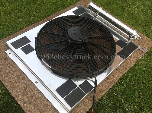
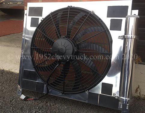
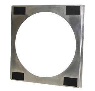
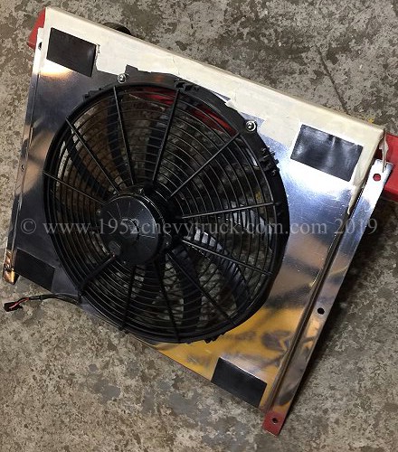
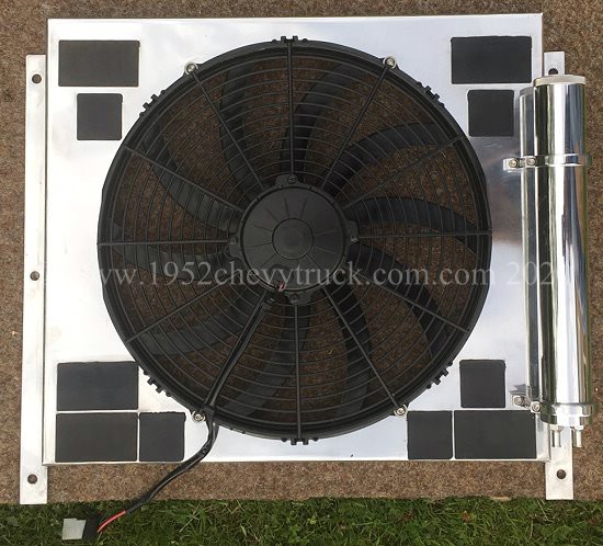
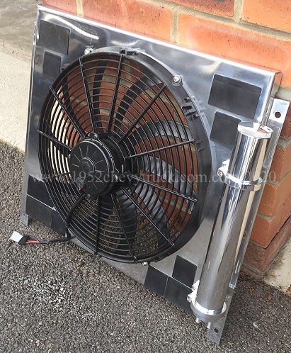
The importance of flaps.
The recommendation is for the fan to be fitted as high as possible on a shroud. The fan is more efficient if fitted to
a shroud as the fan then pulls air through the whole of the radiator. It is also important to use "flaps"
Spall flaps are only $1.00 each (available from Summit Racing and other Hotrod stores). 4 flaps were required,
one in each corner. This means that 4 rectangles needed cutting in the aluminium. Flaps close when the truck is
stationary or moving slowly and the fan is then working at maximum efficiency pulling air through all of the
radiator. When moving at high speed there is a danger than the shroud may restrict air flow and so here the
flaps open, due to the ram air flow, providing additional air flow through the radiator.
There is more information about radiators, shrouds and flaps below.
Update July 2020 Due to research and testing, more than 4 flaps are recommended. See the updated shroud below
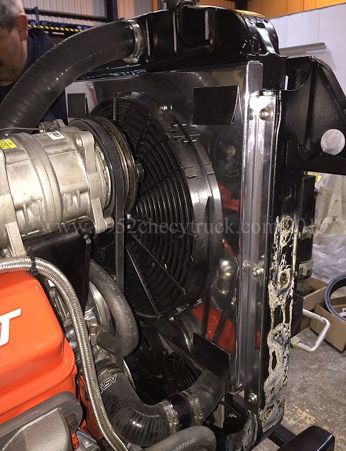
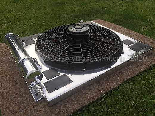
Now for the 2019-20 upgrades -
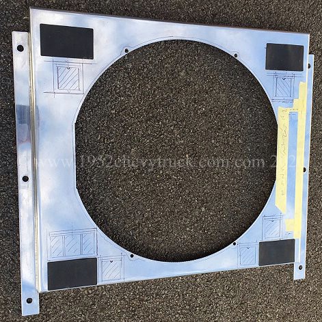
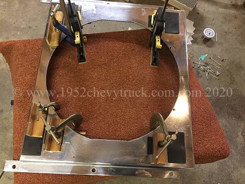
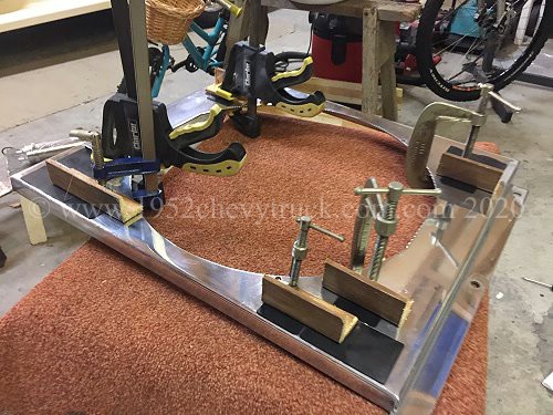
March 2019. The radiator was removed and I made a couple of cardboard templates detailing how I wanted the shroud made.
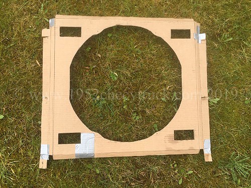
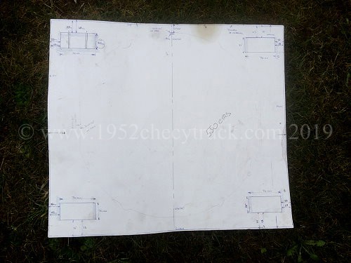
I calculated that considering the thickness of the Spal fan, the shroud should be no more than 20mm thick. That would
leave a gap of about 13mm (1/2 inch) between the water pump pulley and the shroud. I then gave the template to a local
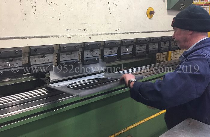
fabrication company and they made the shroud for me using 3mm aluminium. They have a large machine which they
program and it cuts out the shroud. They then use a large folding tool and finally they drilled the 6 mounting holes.
Since my company do a lot of business every month with this company, there was no charge but they told me the
actual cost of this work (using polished aluminium) including materials would have been Ł150 + VAT (about $200)
If anyone is interested in one of these a shrouds let me know but it must be based on the Spal fan.
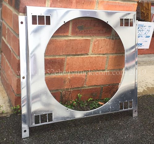
Three small holes above every rectangular slot were drilled to hold the flaps in place.
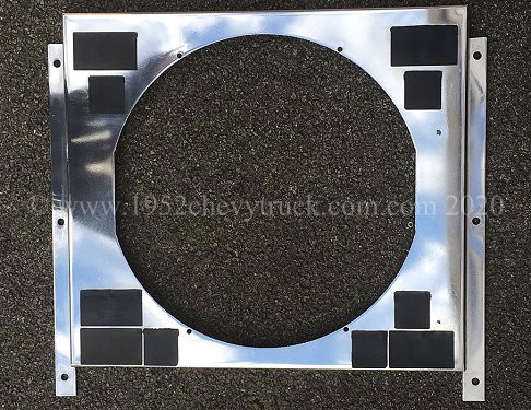
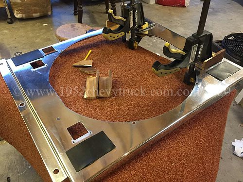
The shroud then needed quite a few hours of work. On my free sample, normal aluminium was used and fold protection
was not used. The folding had left folding marks and so the shroud was polished with 240 grade paper, 600 paper and then
1200 paper (using a orbital sander) it was then polished with "Mothers Mag and Aluminium Polish" (available from Amazon
and many other places). An air tool polishing machine was used to polish the aluminium with the Mothers polish.

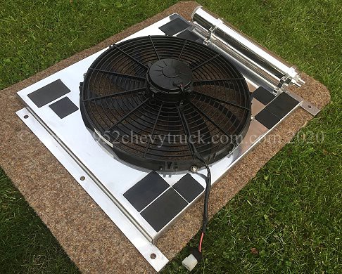
PU adhesive was applied to the rubber pins in the flaps and the small holes in the aluminium and the pins were pushed
into the small holes to retain the flaps. The fan was bolted to the shroud and the shroud was bolted to the radiator.
In both cases, allen key stainless steel button head bolts were used.
The shroud was fitted to the radiator using 6 button head stainless steel bolts.
The radiator in the radiator frame was bolted to the chassis.
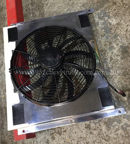
July 2020 update - Shroud flaps. How many? -
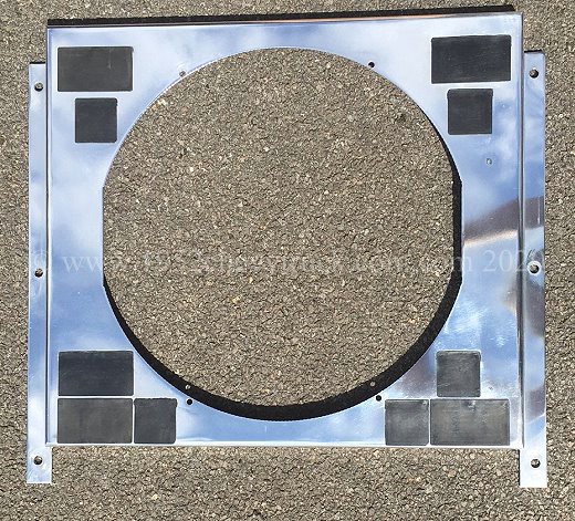
Shown above, before - left and after - right. The new July 2020 mod. to increase the number of flaps.
I have seen manufactures offering shrouds without flaps and some with 4 flaps. The former option is far from ideal and
the latter option, whilst preferable, seems to me to be a guess rather than the result of testing. I have done
considerable testing and have come to the conclusion that more than 4 flaps are needed. Let us consider the reasons.
An electric fan and shroud is a good idea as it keeps the engine cool whilst stationary or moving very slowly in
bumper to bumper traffic. The fan pulls the air through all of the radiator. In this situation, flaps, if fitted,
would be closed. Also in this situation the engine is mostly idling and not under strain and so the fan with
shroud alone (flaps closed) can easily control the temperature.
At the other extreme, 4 flaps assist in the cooling process when speeds are medium to high (30-70mph) At these speeds
more RAM air can get through the radiator if there are flaps. At speeds above 30mph, the RAM air is fast and easily
cools the engine through both the fan opening and through the 4 flaps. The shroud is a restriction to (RAM) air
through the radiator but the air here is so fast (and therefore efficient at removing heat)
only a small number of flap openings are needed.
It is in between these two extremes where the problems can be found. A slow moving truck going up a hill. From about
10mph to 25mph the speed of the RAM air is low and the engine is working hard if going up a hill and that creates
more heat. Temperatures can rise and in these circumstance a fan bolted to the radiator and no shroud could offer
the best cooling (but then the air flow can “short circuit” round the fan, reducing efficiency) What you really need
here is a fan running and as much (slower) air going through the shroud as possible. That is why more than 4 flaps
are needed. Since the air is moving slowly through the radiator, you need as much volume of air to go through as
possible and the volume can be increased with more flap openings. Remember more flaps means more holes in
the shroud and so more routes for the air to get through and cool the radiator.
In tests I believe the best option is to cover all 3 scenarios, especially low speed hill climbing and here the aim
would be to try to double the number of flap openings. The equivalence of 8 flaps means double the extra routes for
the air to get through the radiator (in addition to the route through the fan opening).
Fitting double the number of flaps means doubling the area of the rectangular holes which the flaps cover or uncover.
Since there was not space to fit another 4 full flaps (a full flap has 3 holes, two of 19 x 36mm and one of 27 x 36mm)
it was possible to fit one additional full flap and four 1/2 size flaps (they were slightly larger than 1/2 at 33 x 36mm)
This did not double the air flow through the flap openings but it did increase it by 76% and so very worthwhile.
Now for the modifications.
To accommodate more flaps, the coolant was drained, top hose disconnected, fan electrics disconnected, top hose
removed from radiator and the fan and shroud lifted out. There are 6 bolts, 3 on each side, holding the shroud.
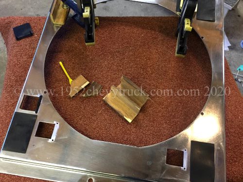
Detailed measuring and marking out followed and the flap fixing holes were centre punched and drilled with a
3.5mm drill. The flap rectangular holes were cut using drills and a jig saw fitted with an aluminium cutting
blade. A cone drill was used and 8mm holes were required to accommodate the jig saw blade. The marking out,
drilling, cutting and filing is easy enough as aluminium is a soft material but it did take a few hours.
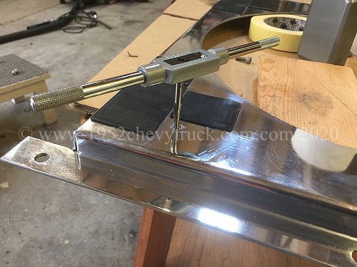
While the shroud was removed, a couple of holes were drilled and tapped to take the brackets for the
new brushed aluminium coolant recovery tank. The holes were 3.8mm and the taps were 3/16" UNC.

Flaps were then fitted as described above using PU adhesive. Always clean the surfaces with “panel wipe” and
score the surfaces so the adhesive has a “key”.
This truck did not have an overheating problem. Moving slowly up hills could see temperatures rise to 200f which
is acceptable. With increased flaps, temperatures do not exceed 190f and this provides a greater margin just in
case of a large hill which could take a considerable amount of time to climb with the engine working hard and
producing more heat. “Spal” flaps came from Summit Racing. The pictures above and below show the finished unit.
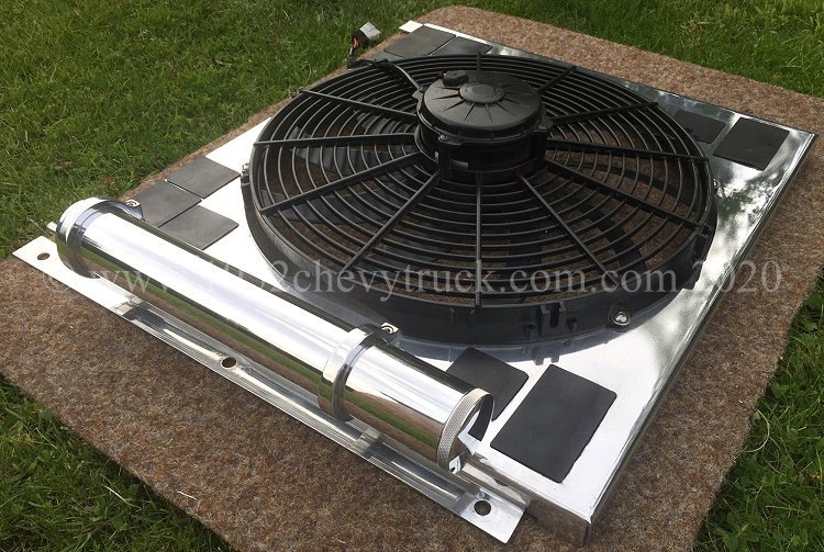
The overflow pipe, see origial notes below from 2019, can now be connected to the bottom of the collant recovery tank.
Also see additional notes below on the coolant recovery tank.
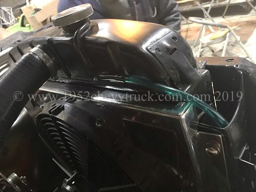
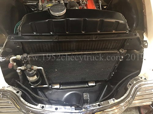
2019 - Overflow pipe mod.
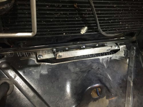
To fit a shroud, the overflow pipe needs to be removed from the right hand side of the radiator. It is soldered down the
right hand side and this will interfere with the shroud. While removing the pipe, it also came away from the fill neck.
It was therefore necessary to take it to "Advanced Radiators" in Newcastle upon Tyne and have a new overflow pipe fitted.
They soldered a new pipe into the neck and ran it horizontally along the inside top of the radiator as shown in the
pictures below. A flexible pipe was then pushed onto the copper pipe and routed down the inside of the radiator
frame where it emerged underneath. Also looking from above, they made a very neat job of routing the copper
overflow pipe over the top of the radiator.
Update July 2020. Please see notes above regarding the coolant recovery tank upgrade.
Antifreeze.
Since the truck has an aluminium inlet manifold, a quality antifreeze is needed and it must be the type
which protects the varoius types of metals in the cooling system. Also note antifreeze can damage
paintwork, especially if it is allowed to dry onto the paint. Wash it off straight away if you spill any.
What type of antifreeze was required?
I did a bit of research on water based coolants / antifreeze which you might find interesting.
“IAT” (original type) like original “Bluecol” - not suitable for aluminium. Ideal for original classic cars and trucks.
“OAT” like “Prestone” - ideal for steel and aluminium but not suitable for copper brass radiators. Ideal if you have an
aluminium radiator or aluminium engine parts like an aluminium inlet manifold.
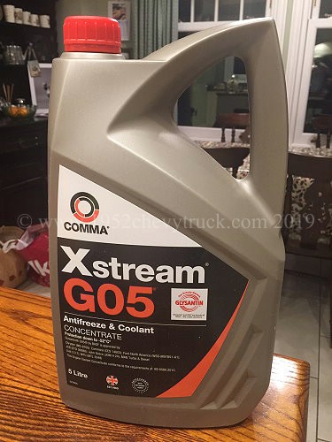
“HOAT” (not exactly a mixture of both but broadly true) also called “G05” - suitable for steel, aluminium and copper
brass radiators. Ideal for my truck as I have an aluminium inlet manifold on the small block 350ci engine but still
running with an original copper brass radiator.
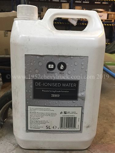
5L of the G05 type is available from Amazon for Ł26.50 (2019). Mixing (e.g. 50/50) with deionised water is better
than tap water and is only Ł1.80 for 5L from Tesco Stores.
Also note all types of antifreeze can damage paint work but OAT is the worst due to the high acid content.
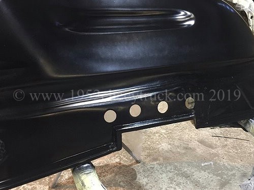
Ventilation holes in the inner fender (wing).
When you put a V8 into a 1947-53 Chevy truck, there is not a lot of room. The engine bay was designed for a
narrower straight 6 engine. It is necessary to use compact header / manifolds and this puts them close to
the inner wings. These header / manifolds produce a lot of heat and so a bit of extra ventilation is a
good idea. You can see 4 holes were drilled into the inner wing right opposite and close to the header
manifolds. This will provide some additional ventilation. Due to the air in the engine bay moving at
a different speed to the air in the wheel well, there will be a pressure difference. Depending on
how fast the truck is going, either hot air will escape, or colder air will enter the engine bay through
these holes. This will happen exactly where it is needed - right next to the hot header / manifold
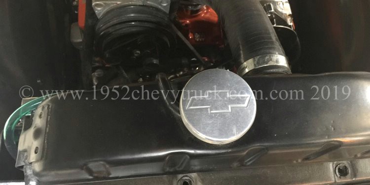
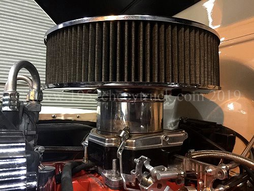
Carburetor temperatures.
Keeping the carburetor cool is also important. This Street Demon 1904 carburetor has a composite base which
insulates it from the engine heat. That means fuel does not vaporise in the carburetor due to it being too hot.
There are more notes further down the page on engine coolant flow, heater hose plumbing, waternecks and
top and bottom hoses, but next transmission cooling will be considered.
Automatic transmission cooling.
If you are running a V8 it is highly likely you will have an automatic transmission. The atf (automatic transmission fluid)
needs to be cooled. Since automatic transmissions were not available for the 1947-53 Chevy truck, there was no extra
cooler built into the bottom of the original radiator. An external cooler is needed. Before starting this discussion
it is important to remember that the number one killer of automatic transmissions is heat!
This is therefore an important consideration.
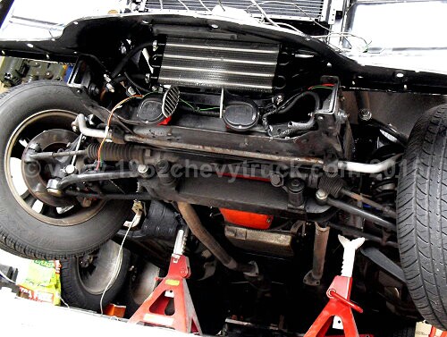
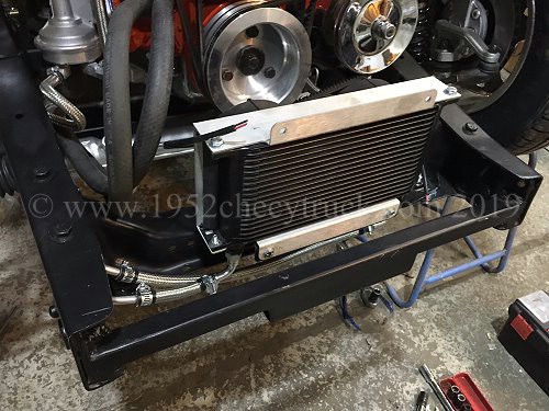
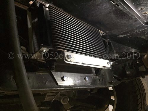
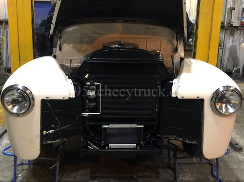
Shown below is the cooler fitted before this upgrade. It is below the radiator and behind the bumper and is in the air flow.
This cooler was originally not fitted in the airflow. In 2007 when this truck was purchased in the States, this "Tube and
Fin" cooler was near the transmission at right angles to the air flow. In July 2010 as part of the first big front end
strip down it was moved to the ideal place below the radiator. The picture below is from 2010.
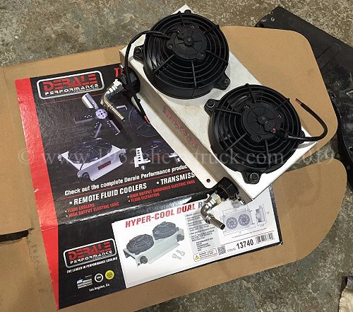
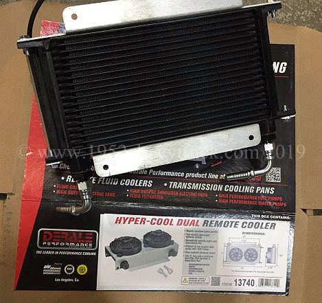
A Derale "Hyper-Cool Dual" 13740 "stacked plate", 10 row cooler (6AN) with shroud and twin fans was chosen for this 2019
upgrade. The fans (wired in parallel) draw a total of 7A and so this must be taken into account when supplying power to it.
"Stacked Plate" coolers are significantly more efficient than "Tube and Fin". I spoke to the Derale representatives
at their trade stand during the SEMA show in Las Vegas in Nov. 2018 and discussed their range of transmission coolers.
There are various types of transmission coolers but the "Stacked Plate" type is the most efficient. All types of cooler work
well when the vehicle is travelling at speed (provided it is mounted in the air flow) but in slow or stationary bumper to
bumper traffic with little air flow, they are not effective. Fan assistance provides the air flow for efficient cooling.
An ideal place to put it the cooler in the air flow is under the radiator behind the bumper. This location restricts the
height of the cooler to about 7 or 8 inches This Derale cooler is 7.5" high (ideal) and 13" wide. It uses two 5" fans.
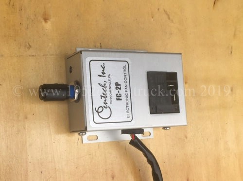
The best way to monitor and control the temperature of an automatic transmission is with a transmission temperature sensor
mounted in the pan and connected to a transmission temperature gauge in the cab. An output from the cab temperature gauge
can be connected to a fan controller. The Centech FC-2P electronic fan controller provides adjustable temperature control
in the cab and connects to the Derale twin fans. The fans will automatically come on when the transmission oil temperature
increases. The aim is to keep the transmission temperature at about 160F. There will therefore be two Centech FC-2P fan
controllers (available from Speedway Motors) in the cab, one for the radiator fan and one for the transmission cooler fans.
More details on how to wire the controller to the fans and monitor the temperatures further down the page.
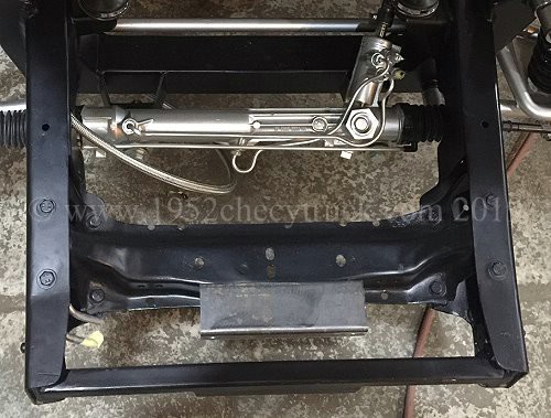
The process of fitting the new cooler during the suspension upgrade is shown below.
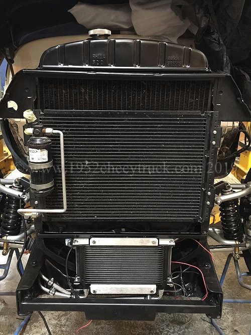
These notes assume you have a 1947-53 Chevy stock radiator of 24” high or an after market one of the same size. If it is
26” high (because it has a transmission cooler in the bottom it would be more difficult to fit this cooler.) Since the
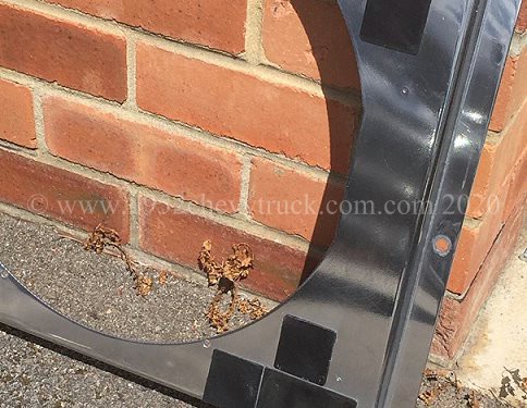
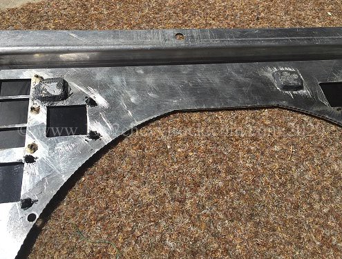
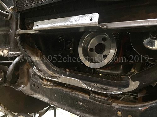
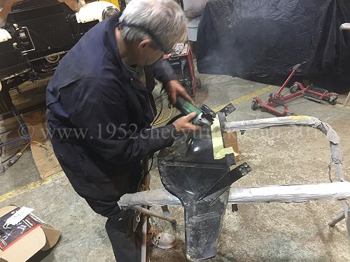
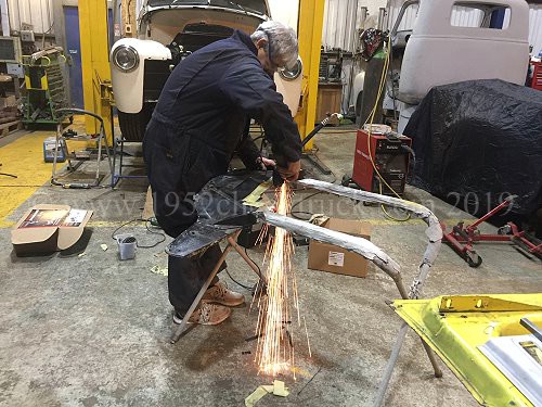
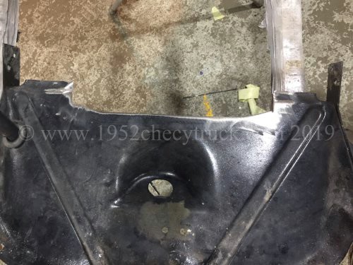
plan was to fit the cooler in the space below the radiator, a fair amount of fabrication was needed. The radiator
frame needs trimming with two curves so that the fans would fit in the gap below the radiator and partly within the
radiator frame. The lower grill ducting panel needed cutting and trimming (as detailed below) so that it does not foul
the top of the cooler. Below you can see the curves cut into the radiator frame so that the fans would push back into
that space. Later the metal was cleaned up and painted black
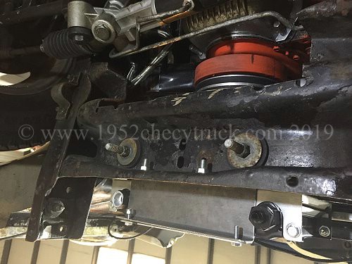
A bracket was made to bolt the cooler to. It was bolted to the cross member which supports the radiator frame.
It was test fitted as shown below and later painted black.
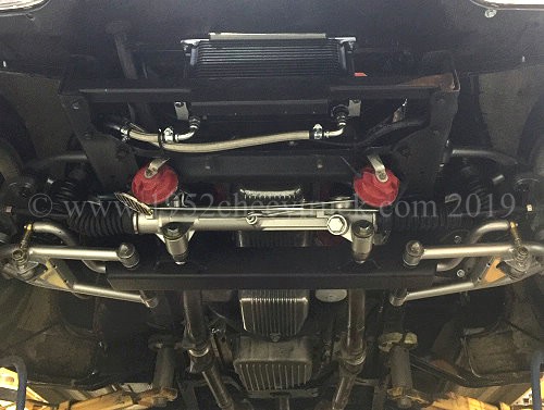
The cooler was test fitted before the radiator was installed. The following 3 pictures show if from behind and from the front.
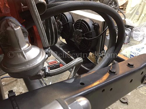
The cooler was removed, radiator installed and cooler refitted after the cooler support bracket was painted black.
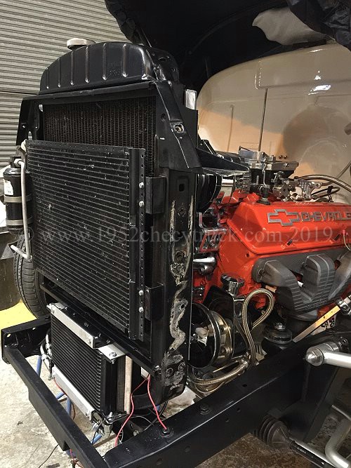
It was now necessary to modify the lower ducting panel as the top of the cooler stopped it from being re-installed.
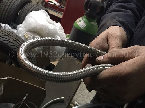
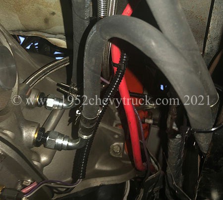
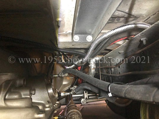
After a test fit, the ducting panel was cleaned up and painted black. Pictures below show it finished. Also in the
pictures below, you can see the 2 x 6AN right angle connectors fitted to the the cooler and then connected to
stainless steel flexible high pressure pipes going into the chassis frame. Inside the chassis, the flexible pipes
connect to aluminium pipes which run through the chassis. At the far end, two more flexible pipes go to the
transmission. The aluminium pipes (below right) came from "Speedway Motors".
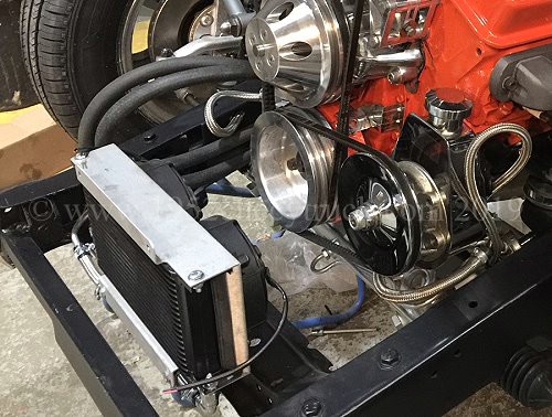
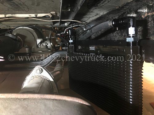
The completed finished assembly of the cooler is shown below. Notice in the right hand picture below are the transmission
cooler, the aluminium finned engine sump pan and the aluminium finned transmission sump pan all in the air flow.
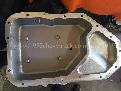
Deep aluminium finned transmission pan.
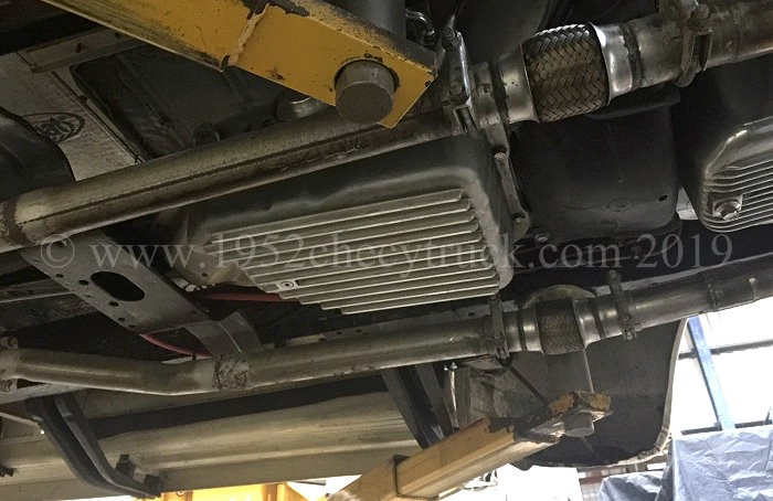
A deep, finned, aluminium sump pan can also assists in cooling the transmission.
The transmission oil (and filter) should be changed at regular recommended intervals.
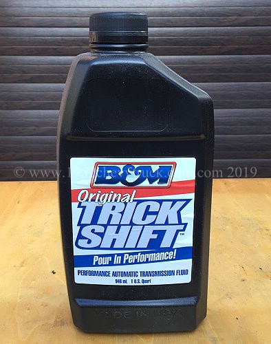
There are many quality makes of atf, I use "B&M Original Trick Shift" which is one of the recommendations
from "Extreme Automatics" who supplied the 200r4 transmission, however, it is no longer possible to buy
this atf in the UK and importing it is difficult as fluids like this have to come by sea.
Durale transmission coolers and Spal fans are available from "Summit Racing" and similar online stores.
More information about looking after an automatic transmission is below.
October 2019 Update. Monitoring and controlling transmission fluid temperatures.
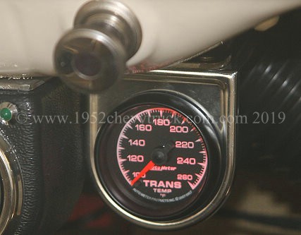
Monitoring the fluid temperature is best done with a high quality gauge system. In my opinion the best gauges are the
"AutoMeter" (e.g. 5957) full scale stepper motor gauges. They are quite expensive at about $190 including the 2-wire
digital sensor but you can sometimes find them $40 or $50 less on Amazon. What is particularly good about these gauges
(apart from their high accuracy) is that they have a large scale (about 300 degrees of pointer rotation) and go up
to 280F but, most importantly, at 180F (the important ideal temperature) the pointer is in the 12 o’clock position.
This makes these meters very easy to see and read. Even easier to read if you wire the gauge illumination to be on
when the ignition is on. As stated this gauge uses an accurate 2-wire digital sensor which needs to be installed
in the transmission pan. (Could be fitted in the output pipe but most opinions agree a good place is in the pan).
The “Centech Inc. Fan Controller” is an excellent product and has served well to control the (radiator fan) engine
coolant temperatures for some time in this truck. A second Centech FC-2P controller was purchased for the transmission.
This was connected to a Derale 13740 transmission cooler which also incorporates a shroud and 2 fans.
The problem is that the Centech controller is designed for use with the simpler smaller deflection analogue type gauges
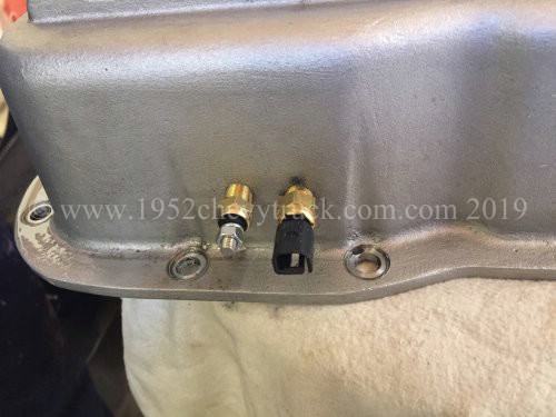
which use a single wire sensor. It cannot be wired into the 2-wire digital sensor. The solution is to fit 2 sensors
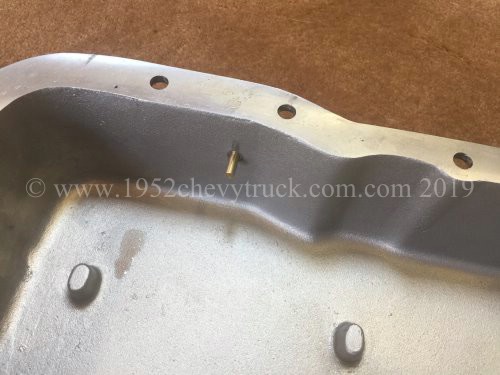
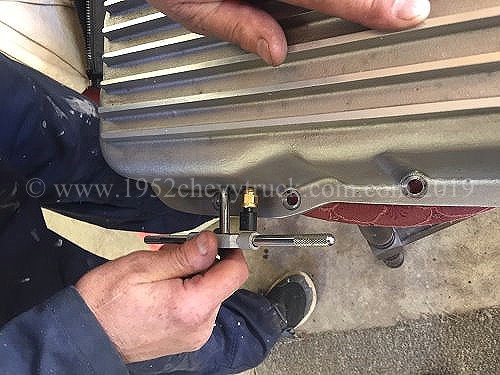
into the transmission pan. Positioning the sensors is quite critical as there is little room inside a transmission
for the sensors to protrude. You have to make sure there is internal room for them. A place was identified on the
right hand side of the 200r4 pan, 2 holes were drilled and tapped with a 1/8 NPT thread.
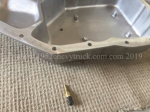
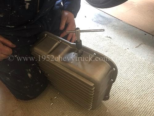
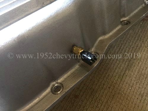
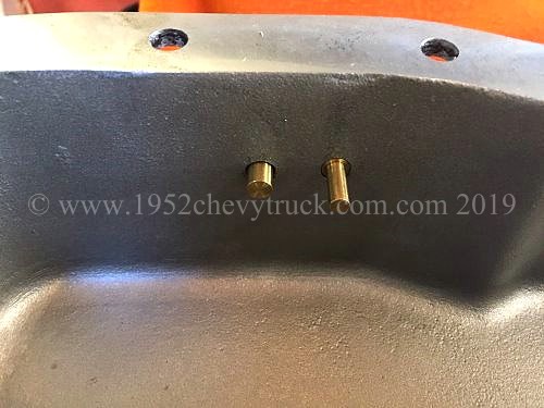
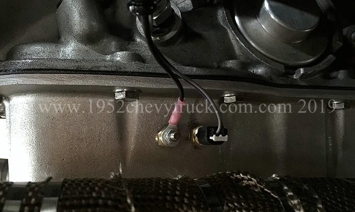
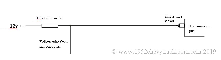
(These two sensors were put in at different times otherwise they would have been done together). The wiring of the
fan controller needs to simulate connection to a (non-existent) analogue gauge and this is done by connecting a
1k resistor to positive and then to the single wire sensor. The yellow wire (also see Centech wiring diagram)
from the fan controller then goes to the far side (not the 12v side) of the 1k resistor. (The 1k resistor taking
the place of the gauge). See the wiring diagram below. Use this with the diagram included with the controller.
Basically here we have 2 separate systems. An accurate easy to read temperature gauge system and a fan
controller / fans / cooler system. The fan controller is fitted in the cab and has a switching temperature
adjustment knob. When you see the transmission temperature on the gauge reach 180F (the 12 o’clock position)
adjust the knob on the fan controller so that the fans come on. A red LED comes on next to the knob to show
the fans are on but you will probably hear them anyway. After a short while they will go off as the
temperature falls (LED then changes to green). Once set, the knob should not need to be adjusted again.
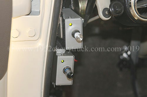
In the cab you can easily see the transmission temperature and you can see and hear the fans go on and off
(LED changing colour and clicking noise from the relay in the controller) as the temperature is held at around 180F.
Estimated costs -
AutoMeter stepper motor type gauge with digital 2-wire sensor (Amazon might be cheapest) - $130 to $187
Centech fan controller (Jegs or direct from Centech) - $90
Single wire oil water temperature 1/8th NPT sensor 0-300F (e.g. from Amazon) - from $8.00
1K Ohm resistor - about $2.00
Derale 13740 cooler with fans (ebay might be cheapest) - about $200 to $245
Total - from $450.00
In use you will find these 2 systems will mostly be used when going up reasonably steep hills in lower gears and
at lower speeds. This is when the transmission fluid can reach (damaging) higher temperatures and you realise
spending that $450 has been very worthwhile.
I use a Stage 2, 200r4 high performance 4 speed transmission from “Extreme Automatics” and protecting that
investment is particularly important but, no matter what the transmission is, it is still worth looking after it.
Temperature control will prevent you from "cooking" the transmission and will certainly prolong it's life.
Update Oct. 2021 Adding a second transmission cooler.
Details of the main cooler under the radiator is above.
The reason for this update was to improve cooling on motorway gradients.
The existing cooler detailed above with shroud and fans was ideal for bumper to bumper driving, however, at
about 50mph on a fairly steep motorway gradient, temperatures would increase. The reason is likely because
there is no cooler in the bottom of the radiator and the fan cooler needed to be larger since the shrouds
and fans do tend to block the ram air at higher speeds. There was not enough space to fit a larger cooler
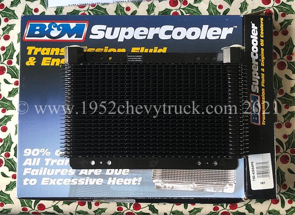
at the front and so the solution was to fit a second cooler. The cooler chosen was an efficient stacked
plate design manufactured by B&M. The ”B&M Supercooler model 70273” from Summit Racing for $106.
This cooler was also thicker than most at 40mm. The cooler was fitted "in series" with the forward
shroud / fan cooler. That is to say, the pipes go through both of them, one after another.
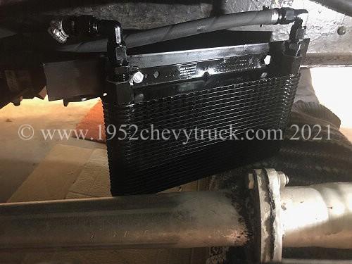
The location of this second cooler was about 1/2 way along the right hand side of the chassis near the
rear transmission support member. There was not enough space for it to be at right angles to the
air flow but it is in the air flow at a reasonable angle for good cooling.
The B&M cooler was $100 from Summit Racing. The transmission was refilled with "B&M Trick Shift".

Looking after an automatic transmission. More information.
If you look after an automatic transmission, it could last a lifetime. Watching others with manual transmissions, regularly replacing
clutches while your transmission is totally reliable is satisfying but it depends on some important maintenance requirements. The
two main rules are to keep the fluid at the correct level and at the correct temperature. The main cause of failure is incorrect
level (too low or too full) and high temperatures. Fluid, filter and gasket should be changed at regular (manufacture recommended)
intervals. The colour and smell of the fluid is also a good guide. If it is going dark or black, or smells burnt it is overdue for
replacing. Whilst low fluid is not good for obvious reasons, too much causes “frothing” and makes the fluid less effective. The
largest vehicles in the world use automatic transmissions and that is because the working parts are immersed in fluid which
lubricates and cools and so automatics are capable of handling more power. Never trust anyone to fill your transmission to the
correct fluid level. This must be done with the engine running (to provide transmission oil pressure) and with the transmission
at working temperature. If the engine is running the transmission is still cold unless the vehicle has been driven. The
transmission must do some work to get up to temperature. That is the only way to check the level. Use the correct fluid and
buy a good make. Generally a transmission fluid tank in the bottom of the radiator is used for cooling. An extra cooling radiator
is recommended for towing but this is also a good idea at any time. The best transmission coolers are “stacked plate” and have
a shroud and fan (like the Durale 13740). That is because in bumper to bumper traffic, everything is getting hot and there is no
air flow. This is when the extra cooler is most needed and without a temperature controlled fan it really has little affect on
the lowing of temperatures. Having driven automatics since the mid 1980s. I have never had one fail. My 200r4 transmission is a
Stage 2, 4 speed automatic transmission from "Extreme Automatics" in the States. It can handle up to 750hp. It is very important
to look after it as a repair or replacement would be very expensive. It uses a tv dent cable connected to the carburettor and if
this is not set up correctly the transmission can be damaged very quickly. How to set that up is complicated and covered elsewhere
on this site but the problem arises due to the danger of low transmission pressure when pulling away. I have a transmission
pressure gauge in the cab, but if the cable is correctly set up there are no issues anyway. 3 speed transmissions (like the TH350)
and more modern transmissions which do not use a tv dent cable do not have this additional set up requirement. Instruments in
the cab are recommended. A Transmission temperature gauge and a transmission pressure gauge will help you monitor your
transmission so that problems can be seen before damage occurs. If you look after your transmission it could last a lifetime.
Radiators, shrouds and flaps. More information.
Whether you buy a cheap radiator from ebay (say $150), or a more expensive radiator from ebay (say $220) or expensive radiators
from the bigger well established companies online, $600 - Ł700 or $800 + there were many people online complaining about failed
new radiators and failed replacement radiators. Usually they have started leaking. If you have a good reliable copper brass
radiator it might be a good idea to keep it. There are pros and cons to using a shroud. If you don't use one, at higher speeds
the air flows through the whole radiator and this provides excellent cooling, however, it is at low speeds, bumper to bumper traffic,
slow manoeuvring etc, when the most heat builds up, in these circumstances, the fan is much more effective if there is a shroud
between it and the radiator. This is because the fan is pulling air through all of the radiator and not just part of it and
the fan creates a low pressure area (partial vacuum) between itself and the whole of the radiator. One effect is rarely considered -
without a shroud, the fan is effectively "short circuited" at it's edges. What this means is that instead of pulling air through
the radiator, it also pulls air from behind itself around it's edges. This is even the case if it is an electric fan and it bolted
directly to the radiator as outside of it's circumference, it will not only be pulling the air in front of it, it will also be
pulling heated air through the radiator in the reverse direction (from behind the radiator) and then back through the radiator
and through the fan. This again is less efficient. Manufactures use shrouds in new cars for a very good reason. They are
efficient at low speeds when the most cooling is needed. "Spal" make shroud flaps. They are only a $1.00 each and probably
4 of them will be needed (depending on the size of the radiator). Flaps open at high speed due to the force of the ram air
coming into the front of your vehicle. At slower speeds (e.g. bumper to bumper, manoeuvring, or stationary), they close partly
due to gravity pulling them down but mainly due to pressure differences. The fan creates low pressure in front of the flap and
high pressure behind it, so it closes. The advantage of all of this is that at higher speeds, the air cools more of the
radiator through the flaps and the fan aperture. At slower speeds when the fan comes on, the flaps makes the shroud
work efficiently by letting the fan pull air through all of the radiator.
Spal flaps are available from many outlets including Summit Racing.
Introduction
When cooling is mentioned most people think “radiators” and whilst radiators are covered in detail here, there is a great
deal more to consider in a comprehensive cooling package. Also covered is the fan, shroud and flaps, ventilation,
water pump, oil pans, heater, hose routing, temperature control and monitoring, building a moulded top and
bottom hose and all of the considerations and equipment for keeping both the engine and transmission cool.
Before looking at the 2019-20 upgrade, let's first look at some previous measures.
1. In 2015 a new water pump was fitted. The water pump is an aluminium finned short SBC water pump from
“Mooneyes Speed Equipment” USA. Part number WAS6917. The pump now costs $155 (2019). Finned aluminium
provides a small amount of additional cooling due to the fins and aluminium is a better conductor
of heat than steel. The pump is in the airflow as it is right behind the radiator fan.
Update June 2020. Mooneyes have discontinued this pump but it is actually manufactured by
"Racing Power Company" (RPC) and is available from them directly on the RPC Website for $126.95.
2. In 2015 a "Hughes" finned aluminium deep engine sump pan was fitted.
Finned aluminium provides additional cooling due to the fins. It helps to cool the oil which is then
pumped around the engine. Also aluminium is a better conductor of heat than steel.
The finned sump pan is in the airflow below the truck. Some people also fit finned aluminium rocker covers.
They will also assist cooling, however, this may be at the expense of appearance.
My preference is for the "Chevrolet" rocker covers from GM Racing.
3. This hood ventilation mod was done in May 2017. Some truck owners may put louvers into the hood but that is a step to
far for me as it affects the original appearance too much, however, there is something you can do.
Straight after driving, if you lift the hood are you greeted with a face full of hot air? Cooling the engine with a fan is all
very well but the hot air needs to go somewhere. Cutting and removing some of the rubber sponge roll at the rear of
the hood lets hot air escape. It may be a small mod but it does help and it does work.
4. Electric fan replacing propeller fan. In may 2007 the old propeller type fan was removed and a temperature
controlled electric fan fitted. In May 2015 the electric fan was replaced with a high performance "Spal" fan.
Also in 2015 the fixed temperature control was changed to the excellent adjustable Centech Inc. FC-2P
electronic fan controller (available from Speedway Motors).
With this controller, the temperature at which the fan comes on can be controlled from inside the cab.
Why is it best to fit an electric fan?.
Modern electric fans only come on when they are needed. Most of the time they are off and there is no fan noise.
Fixed propeller fans reduce horsepower, increase fuel consumption and cool the car when it does not need cooling
which in turn delays the heater from heating the cab. Fixed fans run slow at slow speeds when the fan needs to
be effective and fast at high speeds when the fan does not need to be turning. New cars use electric fans for
all of these valid good reasons. As shown elsewhere on this site, fan manufacturers quote the maximum cfm
(cubic feet per minute) which is the amount of air a fan can move through itself. The absolute cfm rating is not
the complete story. As soon as a fan is bolted to a radiator or a shroud, the cfm count goes down. In tests
it has been shown that Spal fans when bolted up, have a lower decrease in cfm flow rate than most other
fans on the market. Also curved fan blades tend to be quieter than straight fan blades. Fans work best
on a shroud and that is dealt with below as part of this new 2019 cooling upgrade.
Make sure your electrical system has been upgraded to deal with the high currents an electric fan can draw,
especially the transient switch-on currents. The 16" Spal fan in this truck is only 3.5" thick and since
there can be clearance problems between the fan and the pulley, choosing a thin fan is important.
Note, see below, the part of the fan which lines up with the pulley will be much less than 3.5".
Pull or push fans?
This often has to be decided by clearance issues rather than the science. A V8 is shorter than a straight 6
therefore an original truck may not have the space for a pull fan. There should be no such clearance issues
with a V8 modified truck. In my truck there was room for a fan and shroud. The clearance between the fan
with shroud fitted and the engine pulley is about 13mm (1/2"). A fan should be mounted as high as possible
on a radiator and so the fan motor, which sticks out the most, does not line up with the engine pulley.
Whilst the fan may be 3.5" thick max. the part of the fan which lines up with the pulley is much thinner.
(This next bit is where my degree in Physics helps but I think it is also common sense.)
Part of the science of “Fluid Dynamics” is that when a fan is behind the radiator, all of the ram air goes
through the radiator and the fan does not upset or block the air flow. Yes it disrupts the air flow after
the radiator but by then the air has extracted the heat and done its job. When the fan is in front of the
radiator, the fan stops some of the air from going through the radiator and upsets the “lamina flow” of
the air creating “turbulence” before the cooler air gets to the radiator. This results in less efficient
heat extraction. That being said, if the heat extraction is “enough” with a push fan, then this may not be
a significant problem. The lack of space for a pull fan (e.g. with a straight 6 fitted) may take precedence.
Preparing for the 2019 cooling package upgrade.
Let's start by considering whether the radiator needs to be changed -
When improved engine cooling is considered, truck owners will usually look at the effect of the radiator first.
Let us therefore consider whether keeping the original copper brass radiator or changing it for an aluminium radiator is worthwhile.
The quick answer is that it is not as big a consideration as many people realise and either option is fine.
There are advantages and disadvantages with both options but both work really well. Here are the arguments.
Advantages and disadvantages of copper brass radiators -
1. Keeping the original copper brass radiator maintains originality, however, there are some very good aluminium
copies which look the same and maintain originality. Some aluminium radiators do not look the same as original
radiators but are a good fit and perform well.
2. Not changing something you already have saves time and money.
3. Original copper brass radiators by definition are a very good fit but some aluminium radiators are also a good fit.
4. Copper brass radiators are more efficient since copper is a better conductor of heat than aluminium. This is important.
5. If you do not already have a copper brass radiator, a new one will be much more expensive than an aluminium radiator.
This is a key point for many buyers as aluminium radiators are much cheaper.
6. A copper brass radiator is much heavier than an aluminium radiator. This can effect fuel consumption and performance
but these effects are likely to be negligible with this type of vehicle.
7. The manufacture of copper brass radiators is a more skills based process and highly professional companies are
usually involved. These same companies may also make very high quality aluminium radiators, however,
there are some very cheap aluminium radiators on the market of dubious quality.
8. If you have a good radiator already and it has performed well and been reliable for a number of years, why change it?
There are many sad stories on forums about brand new radiators which leak either straight away or shortly after fitting.
In other words why change something which already works well?
I spoke to the CEO of "US Radiators" at the SEMA show in Las Vegas in Nov. 2018. This is a large long standing US company with
a very good reputation. They are market leaders in radiators design and manufacture. All radiators are made in their factory
in the USA which probably explains why their prices are at the upper end of the scale. You can see in the foreground of the
picture of their stand an aluminium radiator for our trucks with a classic original appearance. They also make an original
appearance copper brass radiator for our trucks. This is what he said -
80% of the radiators we make are copper brass and 20% are aluminium.
If you want to buy an aluminium radiator I will sell you a good one but for most applications
it will not be as good as copper brass. We make radiators from aluminium because there is a
demand and to compete with other companies. Many end users request aluminium but they
usually do not understand the principles or they just need a cheaper product.
The two main advantages of aluminium are -
1. Racing as they are light and power-to-weight ratios are important.
2. They are cheap so good if you are on a budget.
Aluminium is about the same price per pound (weight) as copper brass for me to buy in. An
aluminium radiator uses 6-8 pounds of aluminium whereas a copper brass radiator weighs 28 pounds
so material costs with copper brass are much higher. There are many companies selling aluminium
radiators as they are cheap to make due to low material and manufacturing costs. New cars use
aluminium mainly because they cost less but also because they are lighter which has an effect
on performance and fuel consumption. The main advantage of copper brass is that copper is
more efficient at transferring heat than aluminium for better cooling. Whichever material
you use, good core design can improve cooling efficiency by a further 20%.
I asked about shrouds for the fan and he said a shroud makes a big difference to cooling efficiency as, with
a shroud, the fan pulls the air through all of the radiator.
To summarise his advice, both types do the job but it is worth paying the extra for copper brass if you have the budget
and as long as weight it not a prime consideration as it is more efficient at cooling. Although he did not know it,
he had talked himself out of a sale as I already have the original copper brass radiator. I am just going to keep
the one which came with the truck. There is nothing wrong with aluminium radiators but they are not necessarily
“better” as some people have claimed. It all depends on the application. I have, however, taken his advice
regarding shrouds and all of the details about making a shroud are below.
June 2020 update- using the original copper brass radiator and using a Spal fan and Centech controller and before fitting
a shroud, I did not have overheating problems in bumper to bumper traffic or at any time. You might ask why fit a shroud?
I like a "belt and braces" approach and the science tells us a shroud with flaps makes a good improvement in cooling
efficiency. Since fitting the shroud with flaps (see below) there have also been no overheating issues.
I do think much of this cooling efficiency has a great deal to do with the excellent Spal 16" fan.
The importance of flaps.
The recommendation is for the fan to be fitted as high as possible on a shroud. The fan is more efficient if fitted to
a shroud as the fan then pulls air through the whole of the radiator. It is also important to use "flaps"
Spall flaps are only $1.00 each (available from Summit Racing and other Hotrod stores). 4 flaps were required,
one in each corner. This means that 4 rectangles needed cutting in the aluminium. Flaps close when the truck is
stationary or moving slowly and the fan is then working at maximum efficiency pulling air through all of the
radiator. When moving at high speed there is a danger than the shroud may restrict air flow and so here the
flaps open, due to the ram air flow, providing additional air flow through the radiator.
There is more information about radiators, shrouds and flaps below.
Update July 2020 Due to research and testing, more than 4 flaps are recommended. See the updated shroud below
Now for the 2019-20 upgrades -
March 2019. The radiator was removed and I made a couple of cardboard templates detailing how I wanted the shroud made.
I calculated that considering the thickness of the Spal fan, the shroud should be no more than 20mm thick. That would
leave a gap of about 13mm (1/2 inch) between the water pump pulley and the shroud. I then gave the template to a local
fabrication company and they made the shroud for me using 3mm aluminium. They have a large machine which they
program and it cuts out the shroud. They then use a large folding tool and finally they drilled the 6 mounting holes.
Since my company do a lot of business every month with this company, there was no charge but they told me the
actual cost of this work (using polished aluminium) including materials would have been Ł150 + VAT (about $200)
If anyone is interested in one of these a shrouds let me know but it must be based on the Spal fan.
Three small holes above every rectangular slot were drilled to hold the flaps in place.
The shroud then needed quite a few hours of work. On my free sample, normal aluminium was used and fold protection
was not used. The folding had left folding marks and so the shroud was polished with 240 grade paper, 600 paper and then
1200 paper (using a orbital sander) it was then polished with "Mothers Mag and Aluminium Polish" (available from Amazon
and many other places). An air tool polishing machine was used to polish the aluminium with the Mothers polish.
PU adhesive was applied to the rubber pins in the flaps and the small holes in the aluminium and the pins were pushed
into the small holes to retain the flaps. The fan was bolted to the shroud and the shroud was bolted to the radiator.
In both cases, allen key stainless steel button head bolts were used.
The shroud was fitted to the radiator using 6 button head stainless steel bolts.
The radiator in the radiator frame was bolted to the chassis.
July 2020 update - Shroud flaps. How many? -
Shown above, before - left and after - right. The new July 2020 mod. to increase the number of flaps.
I have seen manufactures offering shrouds without flaps and some with 4 flaps. The former option is far from ideal and
the latter option, whilst preferable, seems to me to be a guess rather than the result of testing. I have done
considerable testing and have come to the conclusion that more than 4 flaps are needed. Let us consider the reasons.
An electric fan and shroud is a good idea as it keeps the engine cool whilst stationary or moving very slowly in
bumper to bumper traffic. The fan pulls the air through all of the radiator. In this situation, flaps, if fitted,
would be closed. Also in this situation the engine is mostly idling and not under strain and so the fan with
shroud alone (flaps closed) can easily control the temperature.
At the other extreme, 4 flaps assist in the cooling process when speeds are medium to high (30-70mph) At these speeds
more RAM air can get through the radiator if there are flaps. At speeds above 30mph, the RAM air is fast and easily
cools the engine through both the fan opening and through the 4 flaps. The shroud is a restriction to (RAM) air
through the radiator but the air here is so fast (and therefore efficient at removing heat)
only a small number of flap openings are needed.
It is in between these two extremes where the problems can be found. A slow moving truck going up a hill. From about
10mph to 25mph the speed of the RAM air is low and the engine is working hard if going up a hill and that creates
more heat. Temperatures can rise and in these circumstance a fan bolted to the radiator and no shroud could offer
the best cooling (but then the air flow can “short circuit” round the fan, reducing efficiency) What you really need
here is a fan running and as much (slower) air going through the shroud as possible. That is why more than 4 flaps
are needed. Since the air is moving slowly through the radiator, you need as much volume of air to go through as
possible and the volume can be increased with more flap openings. Remember more flaps means more holes in
the shroud and so more routes for the air to get through and cool the radiator.
In tests I believe the best option is to cover all 3 scenarios, especially low speed hill climbing and here the aim
would be to try to double the number of flap openings. The equivalence of 8 flaps means double the extra routes for
the air to get through the radiator (in addition to the route through the fan opening).
Fitting double the number of flaps means doubling the area of the rectangular holes which the flaps cover or uncover.
Since there was not space to fit another 4 full flaps (a full flap has 3 holes, two of 19 x 36mm and one of 27 x 36mm)
it was possible to fit one additional full flap and four 1/2 size flaps (they were slightly larger than 1/2 at 33 x 36mm)
This did not double the air flow through the flap openings but it did increase it by 76% and so very worthwhile.
Now for the modifications.
To accommodate more flaps, the coolant was drained, top hose disconnected, fan electrics disconnected, top hose
removed from radiator and the fan and shroud lifted out. There are 6 bolts, 3 on each side, holding the shroud.
Detailed measuring and marking out followed and the flap fixing holes were centre punched and drilled with a
3.5mm drill. The flap rectangular holes were cut using drills and a jig saw fitted with an aluminium cutting
blade. A cone drill was used and 8mm holes were required to accommodate the jig saw blade. The marking out,
drilling, cutting and filing is easy enough as aluminium is a soft material but it did take a few hours.
While the shroud was removed, a couple of holes were drilled and tapped to take the brackets for the
new brushed aluminium coolant recovery tank. The holes were 3.8mm and the taps were 3/16" UNC.
Flaps were then fitted as described above using PU adhesive. Always clean the surfaces with “panel wipe” and
score the surfaces so the adhesive has a “key”.
This truck did not have an overheating problem. Moving slowly up hills could see temperatures rise to 200f which
is acceptable. With increased flaps, temperatures do not exceed 190f and this provides a greater margin just in
case of a large hill which could take a considerable amount of time to climb with the engine working hard and
producing more heat. “Spal” flaps came from Summit Racing. The pictures above and below show the finished unit.
The overflow pipe, see origial notes below from 2019, can now be connected to the bottom of the collant recovery tank.
Also see additional notes below on the coolant recovery tank.
2019 - Overflow pipe mod.
To fit a shroud, the overflow pipe needs to be removed from the right hand side of the radiator. It is soldered down the
right hand side and this will interfere with the shroud. While removing the pipe, it also came away from the fill neck.
It was therefore necessary to take it to "Advanced Radiators" in Newcastle upon Tyne and have a new overflow pipe fitted.
They soldered a new pipe into the neck and ran it horizontally along the inside top of the radiator as shown in the
pictures below. A flexible pipe was then pushed onto the copper pipe and routed down the inside of the radiator
frame where it emerged underneath. Also looking from above, they made a very neat job of routing the copper
overflow pipe over the top of the radiator.
Update July 2020. Please see notes above regarding the coolant recovery tank upgrade.
Antifreeze.
Since the truck has an aluminium inlet manifold, a quality antifreeze is needed and it must be the type
which protects the varoius types of metals in the cooling system. Also note antifreeze can damage
paintwork, especially if it is allowed to dry onto the paint. Wash it off straight away if you spill any.
What type of antifreeze was required?
I did a bit of research on water based coolants / antifreeze which you might find interesting.
“IAT” (original type) like original “Bluecol” - not suitable for aluminium. Ideal for original classic cars and trucks.
“OAT” like “Prestone” - ideal for steel and aluminium but not suitable for copper brass radiators. Ideal if you have an
aluminium radiator or aluminium engine parts like an aluminium inlet manifold.
“HOAT” (not exactly a mixture of both but broadly true) also called “G05” - suitable for steel, aluminium and copper
brass radiators. Ideal for my truck as I have an aluminium inlet manifold on the small block 350ci engine but still
running with an original copper brass radiator.
5L of the G05 type is available from Amazon for Ł26.50 (2019). Mixing (e.g. 50/50) with deionised water is better
than tap water and is only Ł1.80 for 5L from Tesco Stores.
Also note all types of antifreeze can damage paint work but OAT is the worst due to the high acid content.
Ventilation holes in the inner fender (wing).
When you put a V8 into a 1947-53 Chevy truck, there is not a lot of room. The engine bay was designed for a
narrower straight 6 engine. It is necessary to use compact header / manifolds and this puts them close to
the inner wings. These header / manifolds produce a lot of heat and so a bit of extra ventilation is a
good idea. You can see 4 holes were drilled into the inner wing right opposite and close to the header
manifolds. This will provide some additional ventilation. Due to the air in the engine bay moving at
a different speed to the air in the wheel well, there will be a pressure difference. Depending on
how fast the truck is going, either hot air will escape, or colder air will enter the engine bay through
these holes. This will happen exactly where it is needed - right next to the hot header / manifold
Carburetor temperatures.
Keeping the carburetor cool is also important. This Street Demon 1904 carburetor has a composite base which
insulates it from the engine heat. That means fuel does not vaporise in the carburetor due to it being too hot.
There are more notes further down the page on engine coolant flow, heater hose plumbing, waternecks and
top and bottom hoses, but next transmission cooling will be considered.
Automatic transmission cooling.
If you are running a V8 it is highly likely you will have an automatic transmission. The atf (automatic transmission fluid)
needs to be cooled. Since automatic transmissions were not available for the 1947-53 Chevy truck, there was no extra
cooler built into the bottom of the original radiator. An external cooler is needed. Before starting this discussion
it is important to remember that the number one killer of automatic transmissions is heat!
This is therefore an important consideration.
Shown below is the cooler fitted before this upgrade. It is below the radiator and behind the bumper and is in the air flow.
This cooler was originally not fitted in the airflow. In 2007 when this truck was purchased in the States, this "Tube and
Fin" cooler was near the transmission at right angles to the air flow. In July 2010 as part of the first big front end
strip down it was moved to the ideal place below the radiator. The picture below is from 2010.
A Derale "Hyper-Cool Dual" 13740 "stacked plate", 10 row cooler (6AN) with shroud and twin fans was chosen for this 2019
upgrade. The fans (wired in parallel) draw a total of 7A and so this must be taken into account when supplying power to it.
"Stacked Plate" coolers are significantly more efficient than "Tube and Fin". I spoke to the Derale representatives
at their trade stand during the SEMA show in Las Vegas in Nov. 2018 and discussed their range of transmission coolers.
There are various types of transmission coolers but the "Stacked Plate" type is the most efficient. All types of cooler work
well when the vehicle is travelling at speed (provided it is mounted in the air flow) but in slow or stationary bumper to
bumper traffic with little air flow, they are not effective. Fan assistance provides the air flow for efficient cooling.
An ideal place to put it the cooler in the air flow is under the radiator behind the bumper. This location restricts the
height of the cooler to about 7 or 8 inches This Derale cooler is 7.5" high (ideal) and 13" wide. It uses two 5" fans.
The best way to monitor and control the temperature of an automatic transmission is with a transmission temperature sensor
mounted in the pan and connected to a transmission temperature gauge in the cab. An output from the cab temperature gauge
can be connected to a fan controller. The Centech FC-2P electronic fan controller provides adjustable temperature control
in the cab and connects to the Derale twin fans. The fans will automatically come on when the transmission oil temperature
increases. The aim is to keep the transmission temperature at about 160F. There will therefore be two Centech FC-2P fan
controllers (available from Speedway Motors) in the cab, one for the radiator fan and one for the transmission cooler fans.
More details on how to wire the controller to the fans and monitor the temperatures further down the page.
The process of fitting the new cooler during the suspension upgrade is shown below.
These notes assume you have a 1947-53 Chevy stock radiator of 24” high or an after market one of the same size. If it is
26” high (because it has a transmission cooler in the bottom it would be more difficult to fit this cooler.) Since the
plan was to fit the cooler in the space below the radiator, a fair amount of fabrication was needed. The radiator
frame needs trimming with two curves so that the fans would fit in the gap below the radiator and partly within the
radiator frame. The lower grill ducting panel needed cutting and trimming (as detailed below) so that it does not foul
the top of the cooler. Below you can see the curves cut into the radiator frame so that the fans would push back into
that space. Later the metal was cleaned up and painted black
A bracket was made to bolt the cooler to. It was bolted to the cross member which supports the radiator frame.
It was test fitted as shown below and later painted black.
The cooler was test fitted before the radiator was installed. The following 3 pictures show if from behind and from the front.
The cooler was removed, radiator installed and cooler refitted after the cooler support bracket was painted black.
It was now necessary to modify the lower ducting panel as the top of the cooler stopped it from being re-installed.
After a test fit, the ducting panel was cleaned up and painted black. Pictures below show it finished. Also in the
pictures below, you can see the 2 x 6AN right angle connectors fitted to the the cooler and then connected to
stainless steel flexible high pressure pipes going into the chassis frame. Inside the chassis, the flexible pipes
connect to aluminium pipes which run through the chassis. At the far end, two more flexible pipes go to the
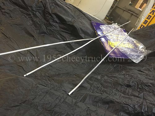
transmission. The aluminium pipes (below right) came from "Speedway Motors".
The completed finished assembly of the cooler is shown below. Notice in the right hand picture below are the transmission
cooler, the aluminium finned engine sump pan and the aluminium finned transmission sump pan all in the air flow.
Deep aluminium finned transmission pan.
A deep, finned, aluminium sump pan can also assists in cooling the transmission.
The transmission oil (and filter) should be changed at regular recommended intervals.
There are many quality makes of atf, I use "B&M Original Trick Shift" which is one of the recommendations
from "Extreme Automatics" who supplied the 200r4 transmission, however, it is no longer possible to buy
this atf in the UK and importing it is difficult as fluids like this have to come by sea.
Durale transmission coolers and Spal fans are available from "Summit Racing" and similar online stores.
More information about looking after an automatic transmission is below.
October 2019 Update. Monitoring and controlling transmission fluid temperatures.
Monitoring the fluid temperature is best done with a high quality gauge system. In my opinion the best gauges are the
"AutoMeter" (e.g. 5957) full scale stepper motor gauges. They are quite expensive at about $190 including the 2-wire
digital sensor but you can sometimes find them $40 or $50 less on Amazon. What is particularly good about these gauges
(apart from their high accuracy) is that they have a large scale (about 300 degrees of pointer rotation) and go up
to 280F but, most importantly, at 180F (the important ideal temperature) the pointer is in the 12 o’clock position.
This makes these meters very easy to see and read. Even easier to read if you wire the gauge illumination to be on
when the ignition is on. As stated this gauge uses an accurate 2-wire digital sensor which needs to be installed
in the transmission pan. (Could be fitted in the output pipe but most opinions agree a good place is in the pan).
The “Centech Inc. Fan Controller” is an excellent product and has served well to control the (radiator fan) engine
coolant temperatures for some time in this truck. A second Centech FC-2P controller was purchased for the transmission.
This was connected to a Derale 13740 transmission cooler which also incorporates a shroud and 2 fans.
The problem is that the Centech controller is designed for use with the simpler smaller deflection analogue type gauges
which use a single wire sensor. It cannot be wired into the 2-wire digital sensor. The solution is to fit 2 sensors
into the transmission pan. Positioning the sensors is quite critical as there is little room inside a transmission
for the sensors to protrude. You have to make sure there is internal room for them. A place was identified on the
right hand side of the 200r4 pan, 2 holes were drilled and tapped with a 1/8 NPT thread.
(These two sensors were put in at different times otherwise they would have been done together). The wiring of the
fan controller needs to simulate connection to a (non-existent) analogue gauge and this is done by connecting a
1k resistor to positive and then to the single wire sensor. The yellow wire (also see Centech wiring diagram)
from the fan controller then goes to the far side (not the 12v side) of the 1k resistor. (The 1k resistor taking
the place of the gauge). See the wiring diagram below. Use this with the diagram included with the controller.
Basically here we have 2 separate systems. An accurate easy to read temperature gauge system and a fan
controller / fans / cooler system. The fan controller is fitted in the cab and has a switching temperature
adjustment knob. When you see the transmission temperature on the gauge reach 180F (the 12 o’clock position)
adjust the knob on the fan controller so that the fans come on. A red LED comes on next to the knob to show
the fans are on but you will probably hear them anyway. After a short while they will go off as the
temperature falls (LED then changes to green). Once set, the knob should not need to be adjusted again.
In the cab you can easily see the transmission temperature and you can see and hear the fans go on and off
(LED changing colour and clicking noise from the relay in the controller) as the temperature is held at around 180F.
Estimated costs -
AutoMeter stepper motor type gauge with digital 2-wire sensor (Amazon might be cheapest) - $130 to $187
Centech fan controller (Jegs or direct from Centech) - $90
Single wire oil water temperature 1/8th NPT sensor 0-300F (e.g. from Amazon) - from $8.00
1K Ohm resistor - about $2.00
Derale 13740 cooler with fans (ebay might be cheapest) - about $200 to $245
Total - from $450.00
In use you will find these 2 systems will mostly be used when going up reasonably steep hills in lower gears and
at lower speeds. This is when the transmission fluid can reach (damaging) higher temperatures and you realise
spending that $450 has been very worthwhile.
I use a Stage 2, 200r4 high performance 4 speed transmission from “Extreme Automatics” and protecting that
investment is particularly important but, no matter what the transmission is, it is still worth looking after it.
Temperature control will prevent you from "cooking" the transmission and will certainly prolong it's life.
Update Oct. 2021 Adding a second transmission cooler.
Details of the main cooler under the radiator is above.
The reason for this update was to improve cooling on motorway gradients.
The existing cooler detailed above with shroud and fans was ideal for bumper to bumper driving, however, at
about 50mph on a fairly steep motorway gradient, temperatures would increase. The reason is likely because
there is no cooler in the bottom of the radiator and the fan cooler needed to be larger since the shrouds
and fans do tend to block the ram air at higher speeds. There was not enough space to fit a larger cooler
at the front and so the solution was to fit a second cooler. The cooler chosen was an efficient stacked
plate design manufactured by B&M. The ”B&M Supercooler model 70273” from Summit Racing for $106.
This cooler was also thicker than most at 40mm. The cooler was fitted "in series" with the forward
shroud / fan cooler. That is to say, the pipes go through both of them, one after another.
The location of this second cooler was about 1/2 way along the right hand side of the chassis near the
rear transmission support member. There was not enough space for it to be at right angles to the
air flow but it is in the air flow at a reasonable angle for good cooling.
The B&M cooler was $100 from Summit Racing. The transmission was refilled with "B&M Trick Shift".
If you look after an automatic transmission, it could last a lifetime. Watching others with manual transmissions, regularly replacing
clutches while your transmission is totally reliable is satisfying but it depends on some important maintenance requirements. The
two main rules are to keep the fluid at the correct level and at the correct temperature. The main cause of failure is incorrect
level (too low or too full) and high temperatures. Fluid, filter and gasket should be changed at regular (manufacture recommended)
intervals. The colour and smell of the fluid is also a good guide. If it is going dark or black, or smells burnt it is overdue for
replacing. Whilst low fluid is not good for obvious reasons, too much causes “frothing” and makes the fluid less effective. The
largest vehicles in the world use automatic transmissions and that is because the working parts are immersed in fluid which
lubricates and cools and so automatics are capable of handling more power. Never trust anyone to fill your transmission to the
correct fluid level. This must be done with the engine running (to provide transmission oil pressure) and with the transmission
at working temperature. If the engine is running the transmission is still cold unless the vehicle has been driven. The
transmission must do some work to get up to temperature. That is the only way to check the level. Use the correct fluid and
buy a good make. Generally a transmission fluid tank in the bottom of the radiator is used for cooling. An extra cooling radiator
is recommended for towing but this is also a good idea at any time. The best transmission coolers are “stacked plate” and have
a shroud and fan (like the Durale 13740). That is because in bumper to bumper traffic, everything is getting hot and there is no
air flow. This is when the extra cooler is most needed and without a temperature controlled fan it really has little affect on
the lowing of temperatures. Having driven automatics since the mid 1980s. I have never had one fail. My 200r4 transmission is a
Stage 2, 4 speed automatic transmission from "Extreme Automatics" in the States. It can handle up to 750hp. It is very important
to look after it as a repair or replacement would be very expensive. It uses a tv dent cable connected to the carburettor and if
this is not set up correctly the transmission can be damaged very quickly. How to set that up is complicated and covered elsewhere
on this site but the problem arises due to the danger of low transmission pressure when pulling away. I have a transmission
pressure gauge in the cab, but if the cable is correctly set up there are no issues anyway. 3 speed transmissions (like the TH350)
and more modern transmissions which do not use a tv dent cable do not have this additional set up requirement. Instruments in
the cab are recommended. A Transmission temperature gauge and a transmission pressure gauge will help you monitor your
transmission so that problems can be seen before damage occurs. If you look after your transmission it could last a lifetime.
Radiators, shrouds and flaps. More information.
Whether you buy a cheap radiator from ebay (say $150), or a more expensive radiator from ebay (say $220) or expensive radiators
from the bigger well established companies online, $600 - Ł700 or $800 + there were many people online complaining about failed
new radiators and failed replacement radiators. Usually they have started leaking. If you have a good reliable copper brass
radiator it might be a good idea to keep it. There are pros and cons to using a shroud. If you don't use one, at higher speeds
the air flows through the whole radiator and this provides excellent cooling, however, it is at low speeds, bumper to bumper traffic,
slow manoeuvring etc, when the most heat builds up, in these circumstances, the fan is much more effective if there is a shroud
between it and the radiator. This is because the fan is pulling air through all of the radiator and not just part of it and
the fan creates a low pressure area (partial vacuum) between itself and the whole of the radiator. One effect is rarely considered -
without a shroud, the fan is effectively "short circuited" at it's edges. What this means is that instead of pulling air through
the radiator, it also pulls air from behind itself around it's edges. This is even the case if it is an electric fan and it bolted
directly to the radiator as outside of it's circumference, it will not only be pulling the air in front of it, it will also be
pulling heated air through the radiator in the reverse direction (from behind the radiator) and then back through the radiator
and through the fan. This again is less efficient. Manufactures use shrouds in new cars for a very good reason. They are
efficient at low speeds when the most cooling is needed. "Spal" make shroud flaps. They are only a $1.00 each and probably
4 of them will be needed (depending on the size of the radiator). Flaps open at high speed due to the force of the ram air
coming into the front of your vehicle. At slower speeds (e.g. bumper to bumper, manoeuvring, or stationary), they close partly
due to gravity pulling them down but mainly due to pressure differences. The fan creates low pressure in front of the flap and
high pressure behind it, so it closes. The advantage of all of this is that at higher speeds, the air cools more of the
radiator through the flaps and the fan aperture. At slower speeds when the fan comes on, the flaps makes the shroud
work efficiently by letting the fan pull air through all of the radiator.
Spal flaps are available from many outlets including Summit Racing.
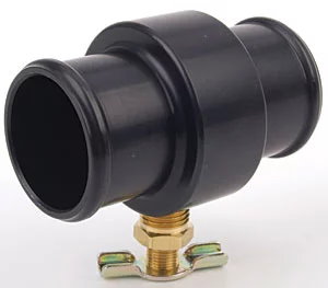
One of the problems with the truck radiator is that there is no drain plug but this can be rectified with an inline 38mm
to 38mm drain adapter. Unlike the radiator (top hose) inlet, which is 1,1/4 inch diameter, the radiator (bottom hose).
outlet is 1,1/2 inches diameter and so a reducer between the 38mm drain plug adapter and the radiator is not needed.
An adapter is needed between the water pump outlet and the drain plug adapter and here an Ash 45mm to 38mm
right angle reducer hose was used. Between the drain plug adapter and the radiator outlet, a 1,1/2 inch hose was
needed with a slight double bend (wiggle). The ideal hose was the Gates 23039 hose and it was trimmed to fit.
Parts -
1. Silicone 90 degree hose reducer 45mm to 38mm from “Ash” on ebay but other companies sell them - Ł13.48
2. JEGS 1.5” to 1.5” (38mm) drain adapter. JEGS Hose Drain Part Number: 555-51155 $23 + shipping.
3. Finding the best pipe with the correct “wiggle” to go from drain adapter to radiator took some time
but the “Jeep Grand Cherokee WK 55116867AA” radiator hose (from ebay) was ideal - Ł17.75
This is actually a 38mm ID "Gates 23039 radiator hose". Also available from RockAuto at $6.00
4. 2 x 2ASS (35-50mm) or 2 x 1MSS (32-45mm) genuine Jubilee stainless steel clips for the hose ends on the drain adapter
and 1 x 2ASS (35-50mm) genuine Jubilee stainless steel clip for the hose end on the radiator outlet
and 1 x 2XSS (45-60mm) genuine Jubilee stainless steel clip for the hose end on water pump inlet.
Jubilee clips are available from "Zoro" and "Rapid Electronics" and from Ebay - about Ł8.00 for the 4 clips.
Only use genuine Jubilee stainless steel clips at they are the best you can buy.
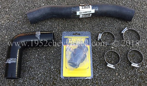
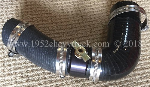
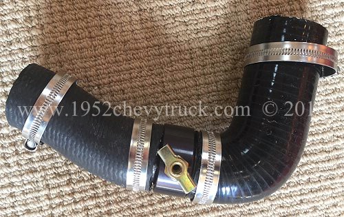
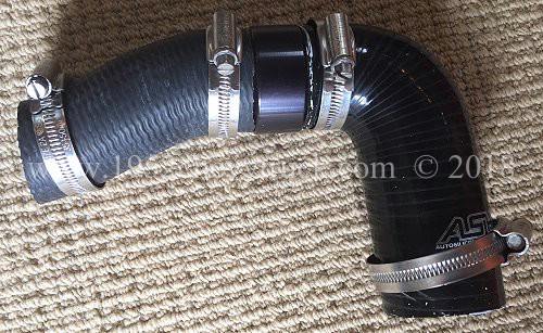
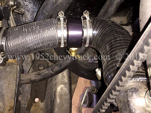
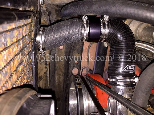
Correct positioning of the clips needs to be considered so that the tightening screw is in a position where easy
tightening can be done with a screw driver. That means for 3 of the clips, the screw should point upwards,
however, since a fan shroud is now fitted to the radiator, the hose clip tightening screw on the radiator
outlet needed to point horizontally and inwards towards the centre of the vehicle. That clip needed is best
tightened from below with a hand through the chassis frame. A little more difficult access but not a problem.
It can also be tightened from above but it is easier from below as from below you can see the screw.
These are high quality hoses and they were trimmed to size. Only the best stainless clips were used.
Breakdowns can happen due to hose failure and so this can be considered as preventative maintenance,
in addition, draining the cooling system is now an easy process.
May 2020 update. The cooling system has been drained several times and the drain
adapter system is easy to access, fast and works perfectly.
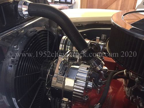
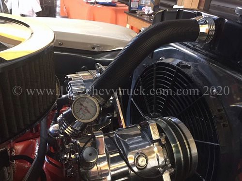
Going from a Gen 1 SBC V8 to an original 52 truck radiator means the hose must start 1,1/2” at the water neck and
finish 1,1/4” (see below 1.25") at the radiator. Whilst reducer hoses are available, a uniform 38mm hose looks best and the
“Gates 26390” Hose Reducer, 1,1/2 to 1,1/4 rubber shim works great. (See below, the sticker round the adapter was removed.)
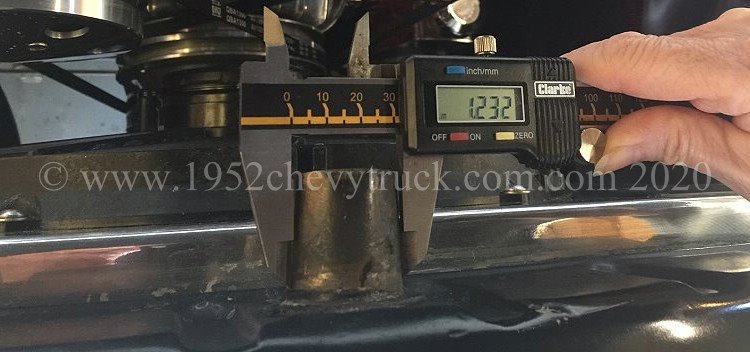
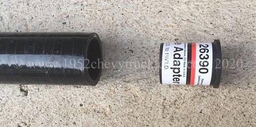
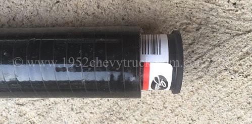
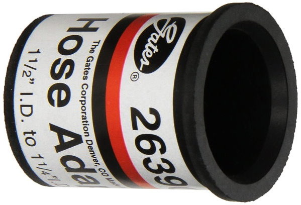
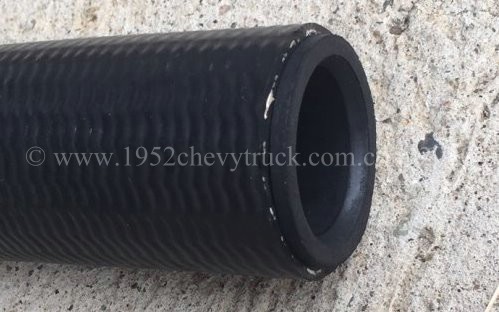
There are a number of 45 degree water necks on the market but most are cast and made in China. The “Billet Specialities”
(BS) 90420, 45 degree water neck swivel is made in the USA from billet aluminium. All BS products are highly polished.
They are more expensive but worth it. It also comes with an excellent o ring to seal against the inlet manifold.
Below left, a cast aluminium waterneck made in China. Below right, a highly polished billet aluminium waterneck made in the USA.
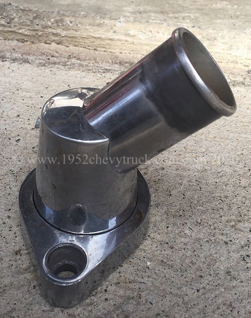
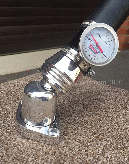
Since this water neck has a 45 degree outlet, a hose with a 45 degree moulded bend is also needed.
The ACDelco 88908297 radiator hose is ideal. It is 20” long and has a 45 degree bend. It can be trimmed to fit.
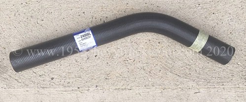
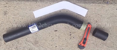
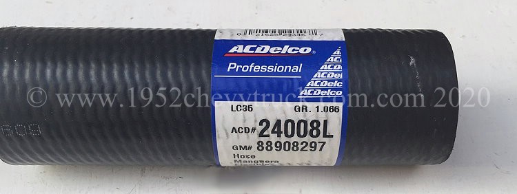
Since there was a need to fit a useful and accurate direct temperature gauge in the top hose (since the outlets in
the inlet manifold were unavailable due to lack of clearance) a temperature sensor hose adapter was purchased.
This adapter is black aluminium and comes with a 1/8NPT sensor outlet. The Summit direct temperature gauge needs
a 3/8NPT outlet and so the adapter was drilled and tapped. These adapters have a strange hose size description
and you have to buy a 40mm adapter to fit a 38mm hose. A short length (60mm long) of Ash wire reinforced silicone
hose was fitted between the water neck and the adapter (but you could just use an off-cut from the GM hose).
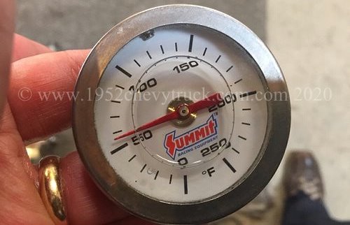
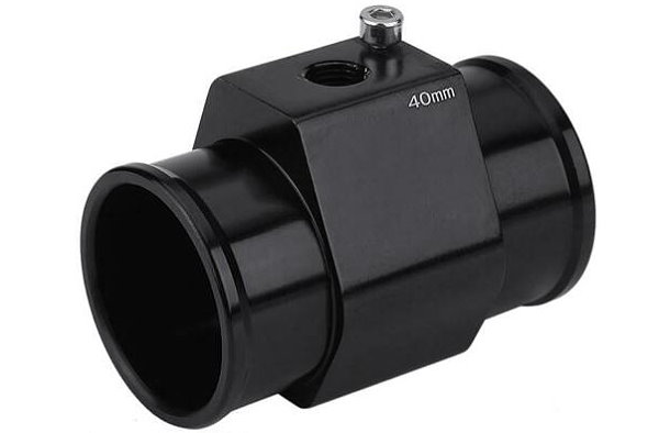
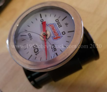
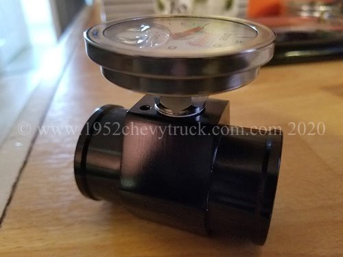
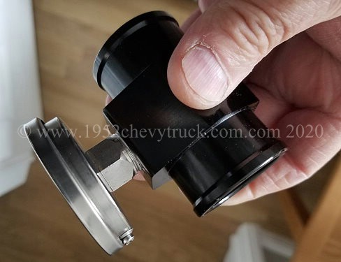
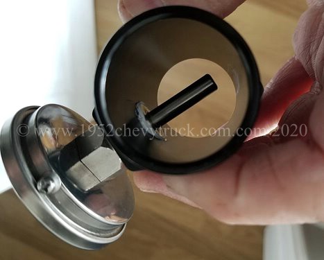
From a trial fit it was clear the GM hose assembly did not exactly align with the waterneck outlet. The water neck
needed raising a little to correctly align it with the rest of the hose assembly. A “Meziere 63433” 1” aluminium
thermostat spacer was purchased and fitted in-between the inlet manifold and the water neck. The Meziere spacer
was not polished to the standard of the BS water neck, so it was polished with “Mothers Aluminium Polish” until
it was as good as the BS water neck. Shown below is the spacer after polishing.
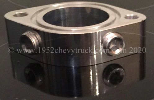
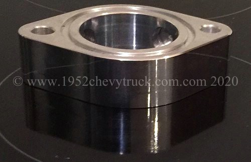
Two Meziere 37812, 3/8NPT Aluminium plugs were needed to plug the two 3/8NPT holes in the spacer. PTFE tape was used to
seal the plugs and also to protect against “aluminium thread locking”. Everything then lined up, fitted perfectly and looked great.
Most importantly there were no leaks and there was no stress on the ACDelco hose as everything lined up. The forces involved in
trying to straighten up the hose cause the stress and the angle of the hose at the inlet is not perpendicular (at right angles)
to the face of the radiator. All of this leads to leaks when the temperature and pressure of the coolant rises.
Stress leaks can be caused by pipes which are not an ideal fit or shape. Trying to get a bend into a reinforced
straight pipe can put considerable stress at the ends at the points of connection, particularly at the radiator inlet.
Shown below is a straight wire reinforced hose with a forced 45 degree bend which can cause stress leaks at the radiator end.
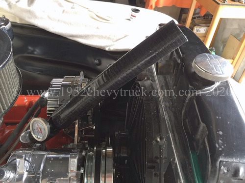
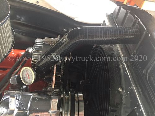
Finally it was important to add to the already very nice appearance with a couple of Billet Specialities 67825 hose end
clips. These polished end pieces look great and hide the integrated hose clips. The 2 hose connections on the
temperature gauge adapter also needed clips and here genuine original stainless steel “Jubilee 1MSS” 32-45mm clips
were used. The clips were rotated to a position which allowed the tightening screws to have easy screw driver
access. Shown below is the complete assembled top hose and also of it fitted to the waterneck. The hose is
moulded at 45 degrees and so everything lines up and nothing is under stress which could result in stress leaks.
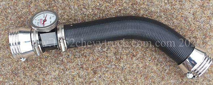
Parts list and suppliers.
(Please note, some items shown in the picture below were not for the top hose project).
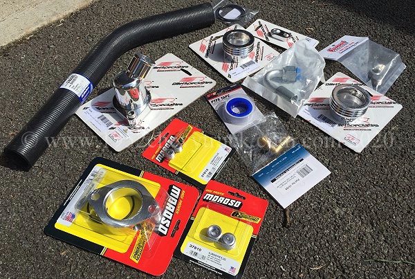
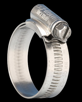
The ACDelco hose come from Summit Racing but is widely available. Also from RockAuto.
The Ash wire reinforced hose came from eBay.
The temperature sensor adapter came from Amazon but comes with a 1/8 NPT outlet (for the sensor).
This was drilled and tapped to 3/8NPT for the Summit Racing temperature gauge.
2 stainless steel "Jubilee" 38mm (32-45mm) 1MSS hose clips from “Zoro” or “Rapid Electronics”.
The Gates rubber shim came from Amazon.com Also from Rockauto.
The Meziere 1” spacer, Meziere plugs, Billet Specialities water neck and BS hose ends came from Summit Racing.
Prices.
• Billet Specialities 90420 water neck $78 (Ł63)
• Meziere 63433 water neck spacer $36 (Ł29)
• Two Meziere 37812 3/8” NPT stoppers for spacer $10 (Ł8 per pair)
• Temperature sensor adapter Ł5 ($6)
• 2 Billet Specialities 67825 hose end clips $22 (Ł18) each
• 2 stainless steel "Jubilee" 1MSS hose clips Ł3 ($4) each.
• Summit Racing SUM-350120 direct temperature gauge $32 (Ł26)
• "Ash" wired silicone hose Ł30 ($37) per metre (optional).
• ACDelco 24008L (88908297) radiator hose $14.99 (Ł11)
• Gates 26390 Hose Reducer 1,1/2” to 1,1/4” rubber shim $14 (Ł11)
Total price.
If you used an off-cut from the ACDelco hose rather than buying a 1m length of Ash hose, the total cost of this
complete top hose assembly (including water neck, spacer and temperature gauge) would be Ł195 ($238).
Note - You also need 2 x 2" bolts to hold the water neck and spacer into the thermostat manifold outlet.
I already had a couple of bolts but this would probably bring the total cost to about Ł200.00 or $244.00
About 50% of that total cost was due to the new waterneck and spacer rather than the actual hose assembly.
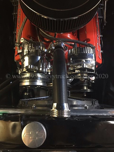
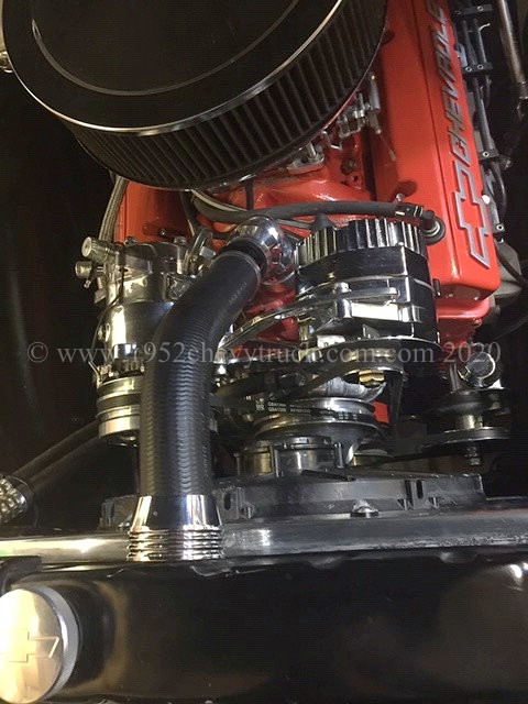
Summit Direct Temperature Gauge Position.
It should be noted that the position for the temperature gauge is above the thermostat. That means it
will only accurately show the correct temperatures when the (160 degree) thermostat is open at higher
temperatures (above 160 degrees). However, the purpose of this gauge is to accurately monitor higher
temperatures to make sure the engine is not running too hot. The normal operating temperature of the
engine would be 180-190 degrees and should preferably be below 200 degrees (210 degrees max).
Therefore this restriction to the gauge’s operating temperature range is not an issue.
When I drive somewhere, and then lift the hood to check the accurate direct gauge temperature,
it usually sits on the 180 degrees mark and that is what I like to see.
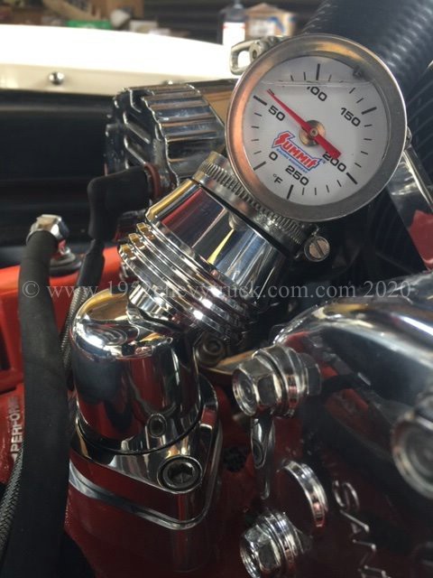
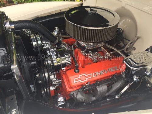
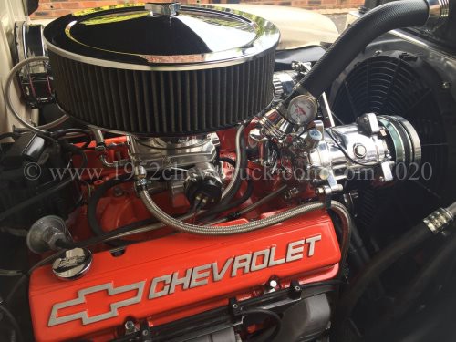
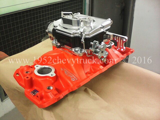
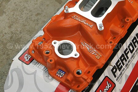
Coolant is usually a mixture of water and anti freeze although some types are not water based. The hottest part
of the engine is at the top (heat rises) and the water pump circulates the coolant through the various channels
towards the top. That means the purpose of the top hose is to take the hottest coolant to the top of the radiator.
The air going through the radiator cools the coolant as it flows through the radiator and the cooler coolant
comes out of the bottom of the radiator, through the bottom hose to the water pump and into the engine.
The heater plumbing is dealt with below. There is a thermostat at the bottom of the top hose and if the engine
has not reached the thermostat temperature (typically 160F) the thermostat will be closed and the coolant will
only circulate around the engine and will not go through the radiator. It follows that putting the temperature
gauge sensor in the bottom hose, is an option, but not ideal for two reasons. The first is that coolant in the
bottom hose will be cooler than in the engine and so the gauge will read low. Secondly, if the thermostat is
closed, there will be no circulation in the bottom hose. The first is the main problem as reading low does
not provide accurate information about the engine getting too hot. The second is not too much of a problem
as when there is no circulation, it is because the engine is cool anyway. When the thermostat opens the
sensor will start working at higher temperatures. Clearly it is best to put the temperature gauge sensor
in one of the ports in the inlet manifold on the top of the engine. If there is no port available, use a 1"
"Thermostat Raising Spacer" in-between the inlet manifold outlet and the top hose water neck. It needs to
be the type of spacer which has a 3/8 NPT port on the side for mounting the sensor and also moves the
thermostat from below the spacer to the top of the spacer thus keeping the temperature sensor below the
thermostat and in the engine coolant flow at all times.
In my truck, there is a 1/2"NTP outlet available in the centre front of the inlet manifold which is clear of
other bracketry or accessories. A 1/2"NTP to 1/8"MPT adapter was needed to adapt the outlet to the 1/8"NPT
sensor. As stated more about the heater below, however, one hose comes from the water pump 1/2"NPT outlet
"sucking" coolant from the heater core outlet and the other hose goes to the heater core inlet
(carrying hotter coolant) from another 1/2"NPT outlet (in the inlet manifold) on the top of the engine.
General notes on coolant plumbing.
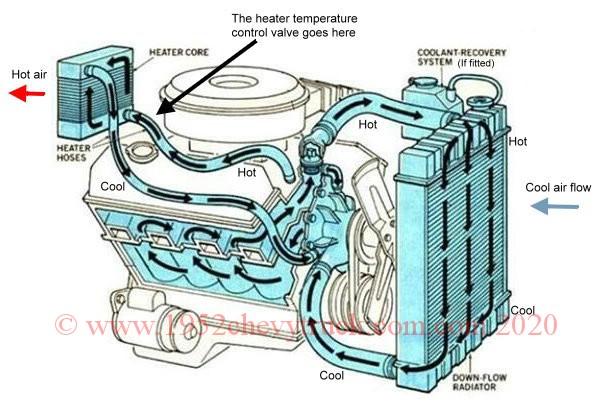
When the water pump is turning, the top of the engine and radiator are at high pressure and the bottom of the
engine and radiator (and pump) are at low pressure. Fluid flows from high to low pressure. Since the pump is
at low pressure, every side port in the pump "sucks". It draws cooler coolant from bottom of the radiator and
it draws cooler coolant from the heater. Many pumps have a large port for connecting to the bottom hose and
a small 1/2"NPT port to connect to the heater. If there are two small heater ports on the water pump, either
can connect to the heater. They are simply there to give you two options on where to connect the heater pipe.
Once you have chosen the easiest pipe routing, the other small port (both will be 1/2" NPT) can be plugged
with a (1/2" NPT) plug. The part of the pump in contact with the engine usually has two outputs to pump cooler
coolant into each bank of the V8. The top hose returns the hotter coolant to the top of the radiator. A port
on the top of the engine / inlet manifold, also sends hotter coolant to the heater (via a temperature
controlled valve). The pictures below show the port in the inlet manifold with a right angled 1/2NPT
to barb connector and with the heater hose pushed onto the barb. The other end of the hose is connected to
the temperature controlled valve under the dash before going into the heater core.
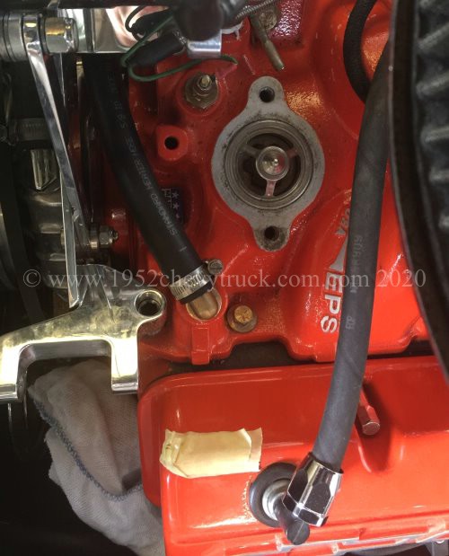
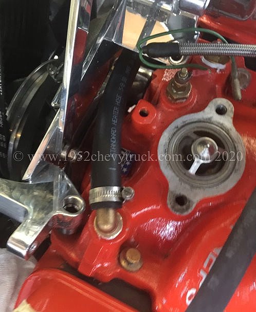
1. The radiator extracts the heat with ram air and sometimes with fan assistance.
2. The heater core extracts the heat with fan assistance when the two control knobs on the dash are turned.
One knob opens the heat control valve, the other knob turns on the fan.
External bypass hose NOT required.
The flow diagram above, if you look carefully, shows a short hose between the top of the water pump and the inlet
manifold. This is called a bypass hose and it helps engine coolant circulation when the thermostat is closed at
cooler temperatures. The diagram is generic and not specific to SBC Gen 1 engines.
This bypass pipe is NOT required on a Small Block Chevy (SBC) Gen 1 engine.
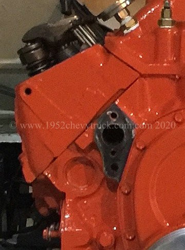
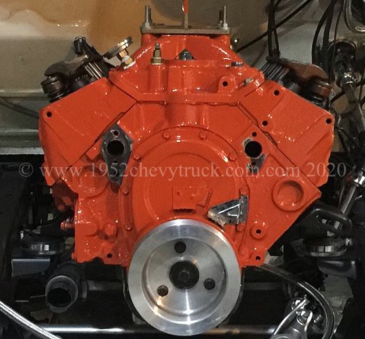
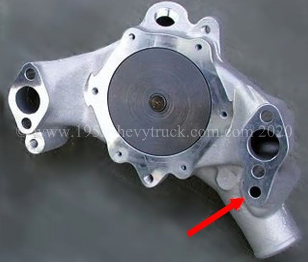
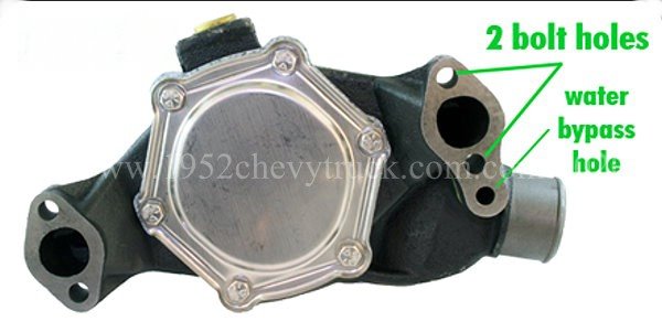
All SBC engines, 1995 and earlier, have an INTERNAL bypass pipe between the pump and the head. All 96 onwards SBC
Vortec heads and Big Block Chevy engines do not have an extra hole / port in the head and do need this pipe attaching.
March 2020. Heater plumbing
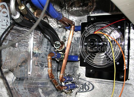
Also read the notes above on "General notes on coolant plumbing."
The hottest part of the engine is the top and so the hot coolant for the heater must come from
one of the output ports in the inlet (intake) manifold. Usually these are 1/2” NPT. An NPT fitting
can be put into one of those ports and the heater pipe connected to it with a “Jubilee” clip.
The hose then needs to be routed to the temperature controlled valve in the heater pipe and then to
the heater core (truck heater) input. Then from the heater core (truck heater) output to the water pump.
The temperature controlled valve needs to go before the heater core input so that it does not let hot
coolant into the heater core until the temperature is turned up in the cab using the heater control knob.
Additional -
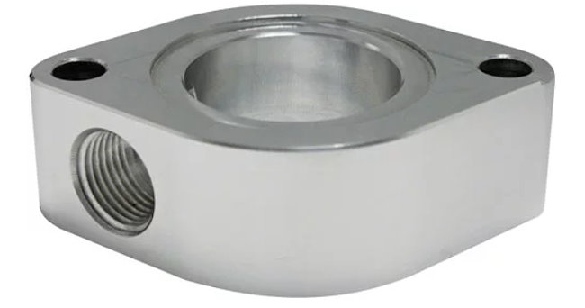
Also read the notes from 2011 on "Installing a truck heater"
More notes on the coolant recovery tank.
This page details a very comprehensive cooling package for the 1947-53 (and 54) Chevy truck with V8
and automatic transmission, however, the cooling system is not pressurised. The overflow from the
radiator drains onto the road which means the radiator needs to be regularly checked and toped up.
A pressurised system also needs regularly checking but rarely needs topping up.
The problem with a pressurised system is that there has to be an unsightly expansion tank and hiding
it away is not easy. Some people do hide it inside the fenders with just the filler cap showing.
If the aim is a clean firewall, even an attractive polished aluminium bottle is best avoided. There
is a possible solution. The "Billet specialities" coolant recover tank was chosen. This is aluminium and
stands to the side of the radiator in an acceptable position and it looks good. It is not a 2 port
(inlet and outlet) pressurised tank but it does work quite well. It has one inlet at the bottom
and a blow out valve at the top. What happens is the overflow pipe is connected to the inlet
connection on the bottom of the tank. When the engine temperature rises, the coolant expands
and overflows into the bottom of the tank. When the engine cools, back pressure
(suction) in the top of the radiator pulls the coolant back into the radiator.
It is said to work quite well and is certainly better than discharging coolant onto the road
without recovery.
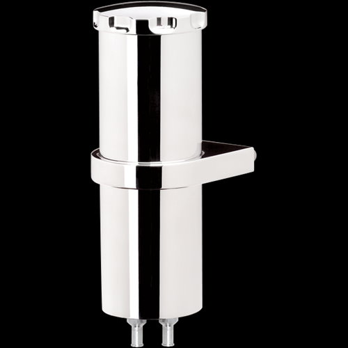
The Billet Specialities coolant recovery tank. This is a company who always produce the highest
quality products made from billet aluminium in the USA and with the highest standards of polishing.
Even the brackets are billet aluminium.
Shown right above - 13,3/8" tall, 2" diameter narrow $105 including the brackets. (Summit Racing)
Shown left above - 8.75" tall, 2.75" diameter $126 including the brackets. (Summit Racing)
Fitting the coolant recovery tank to the shroud.