Introduction
This page will explain what is needed to check castor, camber and tracking and how to do the checks and adjustments.
There are some instruments needed and they are not expensive.
1. Tracking instruments -
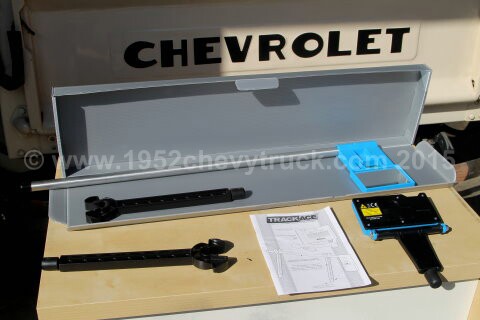
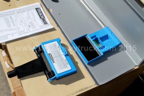
I have used the Trackace gauge regularly since 2011. It is low cost accurate easy to use tool. Highly recommended.
It will soon pay for itself. The Trackace laser alignment gauge is only Ł80.00 (about $120) see https://www.trackace.co.uk
Tracking alignment advice -
There are some a very good instruction videos on the Trackace website. It takes only 2 minutes to set up and use this instrument.
If the tracking then needs adjusting it may take 3 or 4 minutes, then another 2 minutes to recheck. Three adjustments were
needed to set up the tracking on the truck and so adjusting and rechecking took about 15 minutes. Tracking should normally be
"towed-in" about 3mm. A small amount of toe-in makes rear drive vehicles more stable. (Tow-out tends to be unstable.)
While driving, dynamic forces will cause a little tow-out to occur and so a small amount of tow-in will correct that problem,
thus keeping the wheels parallel. 3mm or 1/8th of an inch is recommended. Tracking is measured in degrees when using
a laser or optical tracking gauge but this can be converted to mm or inches using the chart on the Trackace web site.
Note - if you think the castor and camber angles need adjusting, they should be done first followed by the tracking.
2. Camber and castor instruments
The following instruments are required to set these parameters.
1. A castor/camber gauge.
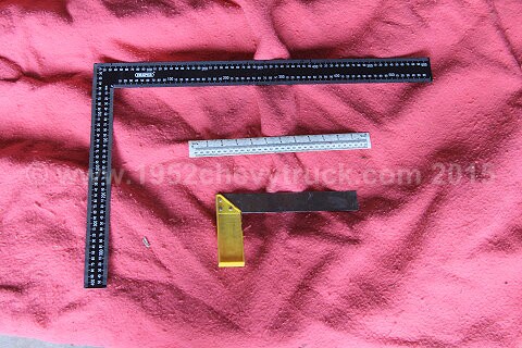
2. An engineers square.
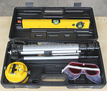
3. A low cost laser level.
4. An angle measuring device. Below you will be shown how to make this with card, a marker pen, a tape measure and the laser.
Included in the picture of the large square is a 30cm, 12" ruler and a woodworking square to illustrate the size of the large square.
It is called a "Draper" "Steel Framing Square" and is available from Tool Station. Price Ł4.71 ($7.00)
Laser Levels often come in a kit but you only need the level. They are available from Screwfix and other online dealers. Ł24.95 ($36.00)
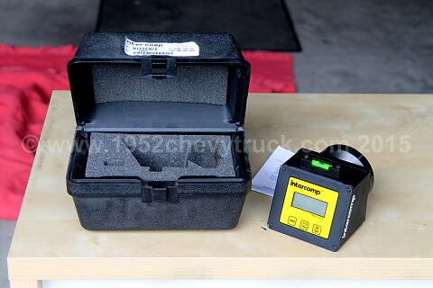
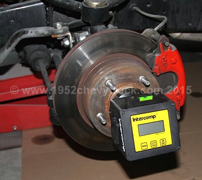
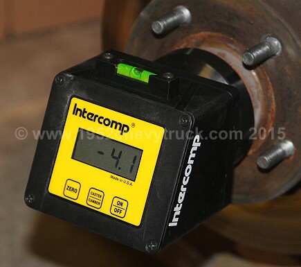
Highly recommended is the "Intercomp Digital Castor Camber Gauge" with magnetic adapter at $339.00 (about Ł220.00).
You have to buy a good gauge and this is as good as they get. Clearly a bit more expensive than the other items but you need it.
Background and theory -
The spelling of the word "castor" in the UK is "castor" and in the USA it is spelt "caster". Since I am in the UK I am using "castor".
It is important to set the two adjustments of castor and camber correctly if the tyre wear is to be even and if the handling of
the vehicle is to optimised. Before starting it is important to park the vehicle on flat level ground with the wheels pointing
straight ahead. The steering wheel should look like the car or truck is being driven in a straight line.
Camber can either be set to zero or a little negative camber can be applied. For best traction and breaking in a straight line a zero
camber is best. For cornering, a little negative camber is recommended. Negative camber is when the top of the wheel is tilted toward
the centre of the vehicle. Negative camber results in the wheel pushing it's width against the corner. For most street cars, anywhere
from 0 to 1 degree of negative camber works fine. A Formula 1 racing car may use up to 4.5 degrees of negative camber. Too much
negative camber can, however, produce uneven tyre wear. It is probably best to set the camber to zero if the majority of driving
is on motorways but up to 1 degree of negative camber is also fine and ideal on twisty country roads. Using the gauge, camber can
be set first but then needs rechecking and most likely resetting after castor is adjusted. Indeed it is necessary to keep going
back and forwards between the two adjustments as adjusting one can affect the other. By going back and forwards,
rechecking and resetting both adjustments, the optimum setting for both can be achieved.
Setting the correct castor on you vehicle is essential for driving and steering stability.
First the technical description – the plane of rotation of the suspension (through the top and bottom ball joints) compared to
a vertical line through the centre of the wheel can be altered to provide negative (-) positive (+) or zero castor angles.
Now the easy description – when thinking of castor, think of “castor wheels on a supermarket trolley”. The wheels rotate at a
point behind the pivot (oops getting technical again). If they were pointing forward, as soon as you push the trolley, the
castors would swivel round and we then have “trailing castors” (or “castor trail”). This is their natural stable mode of
operation. They would have “+ castor” (castor trail). If pointing forward they would have “– castor”
Clearly for stability + castor is required.
If the suspension on your car, truck or hotrod has “– castor” it is like the castors on the supermarket trolley pointing forwards.
When moving forwards, your wheels can’t swivel through 180 degrees like the castors on a shopping cart as they are tied together
by the steering rack (and other things e.g. sway bar etc.) BUT THEY WOULD BE TRYING TO TURN BACKWARDS! The steering feels
unstable, you need to have a tight grip on the steering wheel and you have to concentrate more to keep the vehicle moving in a
straight line. As the vehicle moves forward and hits bumps in the road or the steering tries to turn, the wheels try to swivel
backwards. The steering is unstable and you have to concentrate and work hard to keep the vehicle moving in a straight line.
With + castor, the steering is stable and the suspension geometry has a "trailing castor angle". The steering is in it’s natural
mode of dynamic balance (oops technical words again) but hopefully by now you have the idea. About 4 degrees of “+ castor” is
fine. Some people recommend, 5, 6, 7, 8 or even 9 degrees of “+ castor” but 4 degrees is a good starting point and is probably
an average stock value used by car manufacturers. After that is a matter of experimentation.
A good site showing castor, camber and tracking is at - www.aa1car.com More information at Rod and Custom Magazine
Setting up the vehicle to measuring and setting the “castor” or "camber" angles.
First check how far the vehicle is from the ground before removing the wheels. For example make a note of how high a reference
mark on the front bumper bar is from the ground. (I used the bottom if the bumper as a reference.) More about this later.
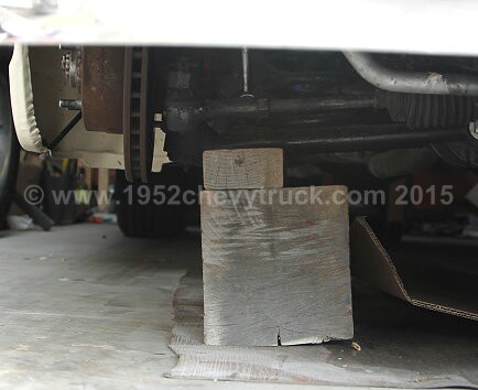
Remove the wheels using a jack but the suspension must not be left hanging. It must be under load therefore the car / suspension
must be lowered onto blocks. If a central trolley jack is used it can be left in place but lower it a little so that it is just clear
of the vehicle. There may be special devices to lower the suspension onto but I just use blocks of wood. It is probably a good
idea to put a rubber pad on top of the blocks to protect the suspension. It must be possible to rotate the steering but with
the suspension still under load. The blocks need to be put under an appropriate lower suspension part and as far outboard as
possible without fouling the turning circle. Now back to the height, use enough blocks so that the height of the front bumper
is the same as when the car has it's wheels refitted and in normal driving mode. Make sure the blocks are stable. (If the jack
is not left in place, make sure you have other back-up supports in place just in case the car were to falls off the blocks.) To
summarise, the car or truck should be at the same height and with the same loads on the springs as if the wheels were still on.
Checking the “camber” angle.
This is done with the Intercomp Digital Castor Camber Gauge. Just follow the instructions provided with the gauge.
Make sure the steering wheel is set as if the car was travelling in a straight line. Level the gauge using the spirit level on the top
of it. Use the buttons to select camber and check the reading. Usually zero is ideal or up to 1 degree of negative camber.
It is also possible to check this with the large square providing the garage floor is flat and level. Put the square on the floor
and up against the brake disc rotor. For zero degrees the disc rotor should be exactly square or at 90 degrees to the ground.
This is an important extra check as it should agree with what it says on the gauge. If the gauge says zero the disc
should be at right angles to the level ground.
If the camber angle does need adjusting the procedure to do this is explained below.
Preparing to measuring the “castor” angle.
The excellent "Intercomp Digital Castor Camber Gauge with magnetic adapter" is now going to be used for castor checking.
Caster is best set by comparing with stock castor angles on new cars which have not ever been tampered with. A typical stock
castor angle would be 4.2 degrees. Anything from 4 to 6 degrees would be the norm. This can be checked by measuring the
castor angles on two or three new cars.
When checking the castor angle, as stated, the wheels must be removed and the suspension lowed onto blocks. It is now
necessary to rotate the steering 20 degrees to the right and 20 degrees to the left of centre while using the gauge to find a
castor measurement. It is important to be able to turn the wheels each way by that amount. There may be special
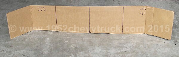
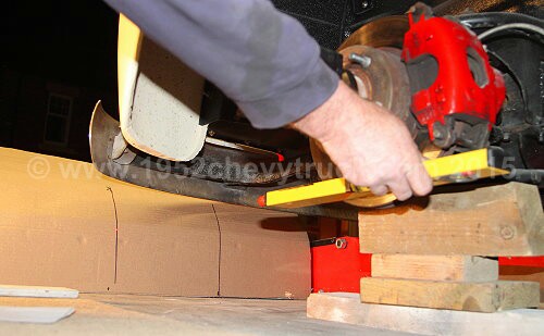
instruments to do this but we are going to use a long piece of cardboard and prop it up just forward of the vehicle
and parallel to the front bumper. This will act as a screen. This screen will need 3 marks (vertical lines) drawn on with
a marker pen. One will represent centre, one will represent 20 degrees to the left and one 20 degrees to the right.
Taking the card screen, draw 3 lines at 29cm apart. i.e. a centre line, one line 29cm to the left of centre and one line 29cm to
the right of centre. The screen must be placed 78cm from the centre of the wheel or centre of the brake disc. That is where
the large square can help, use it to project the centre of the wheel / disc / hub to the ground. Using a tape measure make
sure the card screen is 78cm forward of that point. I have now found a thin piece of wood 78cm long is better than a tape
measure as the fixed length of wood makes it is easier to reset the screen distance than using a flexible tape measure.
The wood can be left in place as it is quite easy to knock the screen over and then the distance needs resetting. Marks
on the garage floor also help especially a dot to re-position the centre of the screen. (The reason the lines at 29cm
represent 20 degrees comes from trigonometry - the inverse "Tan" of 29/78 is 20.39 degrees. Pretty close!)
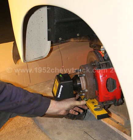
The centre line on the card should be lined up longitudinally with the centre of the front wheel. If you drew a line from the
centre of the back wheel forwards through the centre of the front wheel it would go through the centre line on the card.
also, as a second check, if the steering is correctly centred (looking at the steering wheel) when putting the straight edge
laser on the brake disc, (disc rotor) the beam should also hit the centre line on the card (see above).
Using the gauge to check the castor angle.
Checking the castor angle can now be done by referring to the instructions which come with the castor camber gauge but briefly -
with the laser beam on the centre line, the gauge is made level with the spirit level on top of the gauge. Using the steering wheel
the laser beam is moved to the inboard 20 degree mark on the card and the gauge is set to zero. The steering wheel must then
be turned so the laser beam hits the outer 20 degree line on the card. The castor angle can then be read from the gauge.
Repeat for the other side. Always start / set the zero inboard and read the castor angle outboard.
This principle is the same for every vehicle.
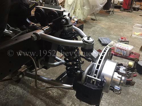
Being Mustang II specific the adjusters on the upper suspension arms must now be identified.
How to adjust camber on a Mustang II suspension.
This truck uses Mustang II tubular suspension (from Speedway Motors) but note Mustang II stock suspension is adjusted
in the same way. There are "turrets" (sometimes called "hats" or "top hats") welded to the Chassis (Frame). These turrets
have slots (which run transversely across the vehicle) and the upper suspension arm bolts into these slots. The slots run
across the turrets perpendicular to the frame rails (chassis rails). It is therefore easy to see how camber can be adjusted.
If the upper suspension arm is adjusted to the end of the slots ... inboard, the top of the wheel will tilt inwards and there
will be - camber. If bolted at the end of the slots outboard (furthest away from the frame (chassis rails), the top of wheels
will be tilted outwards giving + camber. At some point towards the middle of the slots (probably both slots equally) zero camber
will be achieved. The best method of making adjustments is to loosen the nuts under the turret only slightly so that, with a
lever, or pry bar, the upper suspension arm can be slid inboard or outboard but the arm still grips the turret enough not to
slide (the tendency is to slide inboard due the weight forcing it in.) With the castor camber gauge in position as shown in
the pictures above (using the magnets which hold it in position in the centre of the hub) the lever can move the upper arm
in the slots until the gauge reads zero. (or whatever camber is required but zero would be recommended for best traction,
breaking and even tyre wear.) Moving the upper arm equally in the slots can achieve this zero camber setting. Alternatively,
if the garage floor is level and flat, and using a pry bar to move the bolts in the slots, the large square can be used to
set the brake disc rotor at 90 degrees to the floor to achieve zero camber.
(This is a good starting point but this may not give a good castor setting ... so read on ..)
How to adjust castor on a Mustang II suspension.
To adjust castor, the plane of rotation of the turning movement between the upper and lower suspension ball joints
must be altered compared to the vertical, That is a mouthful!!! and is best explained by looking at the following two
pictures. The spring and shock absorber is fairly vertical and so we can use them as a vertical reference point.
When looking at the pictures below remember the sway bar is forward of the disc and the brake calliper is behind the disc
and so the front of the truck is towards the right.
If the castor angle has been checked and found not to fall between +4 and +6 degrees an adjustment is needed.
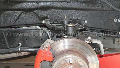
The first picture below shows the right hand side of the truck with wheel removed. Here you can see the upper suspension
arm ball joint (rotation point) is forward of the top of spring/shocker. i.e. is forward or towards the front of the truck.
This is - (negative) castor. If that is difficult to follow, notice the grease nipple (above the disc) closest to you is
forward or to the right of the grease nipple further away. This is equivalent to the castor wheels on a
supermarket trolley pointing forwards. It is unstable. The steering will be difficult to control.
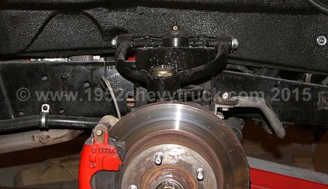
The second picture (below) is again a picture taken of the right hand side of the truck and here you can see the upper
suspension ball joint (point of rotation) is rearward of the spring/shocker. i.e. towards the back of the truck. This
is + (positive) castor. The grease nipple closest to you is rearward of the nipple further away.
This is "castor trail" and is stable and recommended.
The first or top picture (above) shows 4.5 degrees of - castor.
The lower second picture (above) shows 4.5 degrees of + castor and would be the recommended adjustment.
To adjust the castor angle we go back to the slots (the same slots adjust the castor and the camber angles). To achieve
+ castor the bolt through the front slot must be more outboard than the bolt through the rear slot. This results in a
twisting action which makes the suspension's plane of rotation tilt backwards (rearwards - towards the back of the truck),
however, as soon as this is achieved, since the bolts through the slots have been moved this upsets the camber and so both
camber and castor must be continually checked with the Gauge. When the bolts through the slots are in the correct positions
the castor becomes +4.5 and the camber zero. To achieve this it is "probable" that the bolts through the slots might be as
follows ... the rearward bolt might be a little inboard of the centre of the slot and the forward bolt (towards the front
of the truck) may be a little outboard of the centre of the slots. (This inboard and outboard refers to the direction across
the truck). In our case we found that with 4 degrees of + castor and zero camber the front bolt was more than a just a little
outboard. It was almost at the end of the slot outboard (away from the frame (chassis)). No doubt all vehicles will vary
from what was found with this truck but hopefully this example provides a guide or a rule of thumb to achieve a good set
up. It is difficult to explain and it may be difficult to follow this procedure but when you actually do the checking with
a gauge and make the adjustments, it all becomes much more understandable and clear. A bit of practice is needed.
After the castor and camber were correctly adjusted, the tracking was set to a toe-in of 3mm
Also note,
Too little + castor, (or any amount of - castor) will result in steering instability and wandering.
Too much + castor (e.g. +7 or 8 degrees) can result in two problems -
1. Excessive road shocks when travelling over bumps.
2. Excessive steering wheel "snap-back" while exiting a corner.
4.5 degrees seems to be about right but some recommendations quote 4 degrees + or - 0.5 degrees.
Finally please note that unequal castor settings, (e.g. more on one side compared to the other side) can make the steering
want to pull to one side. It is permissible to increase castor on one side compared to the other by 1/4 of a degree to
compensate for the slight banking from the curb to the crown of the road and this depends on whether the country you
are in drives on the right or the left but this affect is very small and probably not worth worrying about. However,
if the vehicle is pulling a little towards the curb this small adjustment may be worth trying.
Tracking adjustments
Once the castor and camber angles have been correctly adjusted, the tracking needs to be checked and adjusted.
Remember 3mm of toe-in is ideal as explained at the top of this page. There is no need to explain how to do
this as the instruction videos on the Trackace website are excellent. Just follow them.
Road Testing.
This whole setting up process was first done on the 9th Sept 2011 but it has been repeated again in 2015 after more changes
were made to the truck. The road testing refers to 2011 as the resetting in 2015 simply brought the alignment back to what
it should be after the 2015 changes were made. First consider what the truck's steering was like prior to the setting up of
camber, castor and tracking. Over the previous year or so there had always been a show deadline and putting the truck back
together for the next show did not provide time for setting up the suspension. Since fitting the new tubular suspension,
camber had been set with a set square and tracking had been set with a tape measure. Castor had never been set up. Before
the last show at Nebworth Park, tracking had been set up with the new laser alignment system. With the stock Mustang
suspension, again the castor had never been set up but bump steer and wandering had been eliminated. When driving to the
Nebworth show it was necessary to hold the steering wheel with both hands. You could hold it with one hand but two were
better. Concentration was needed. When the castor angles were checked, they were found to be -4.5 degrees on both sides.
That is probably due to setting up the slots equally when we now know the front slot should have the bolt pulled outboard
and the bolt in the rear slot needs to be pushed inboard. After correctly setting up the castor to +4.5 degrees as detailed
above with toe in at 3mm, the handing and drive-ability of the truck was transformed. With a modern car "one finger steering"
is not recommended but possible. That is to say little concentration is needed to keep a modern vehicle driving in a
straight line, at high speed, or any speed. First impressions while driving to the main road were that the steering was
returning to the centre after cornering. Accelerating out of a corner and the steering was wanting to straighten. This
was encouraging. (Remember the wheels on a shopping trolley want to rotate backwards. With + castor a steering wheel
wants to return to centre and the front wheels want to point straight ahead.) On the motorway speed was increased to
50mph and no real concentration was needed to hold the steering wheel. It was not necessary to try the one finger test,
with both hands off the wheel (not recommended) the truck drove straight and true. Increasing speed to 70mph seemed to
be even more stable. The steering just seemed to want to continue in a straight line without driver input. It was
possible to relax and know the truck would be totally stable and predictable.
Update 2015.
In 2015 stronger springs were fitted which increased the height of the front of the truck (which was too low). The tyre
profile was also increased. The castor camber and tracking were then reset. This all had the effect of a massively
improved ride and it also reduced the turning circle. More information about this update.
Update 2019.
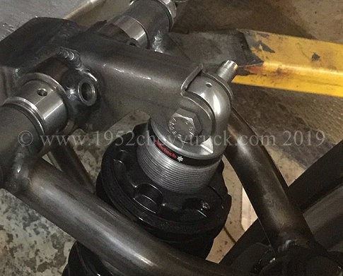
In 2019 a new front suspension was fitted. This is the TCI Custom ifs and one of the reasons it was chosen was
because it uses a better system for setting caster and camber. Instead of using slots like the Speedway ifs
it uses cams which are adjusted with a tool. That means the adjustment is on the top and so trying to access
nuts underneath with the springs in the way to tighten the slot bolts is now a thing of the past. cams are
much easier. Whether it is slots or cams, the process is the same as detailed on this page.
Conclusion.
This whole project has been a complete success and hopefully, if anyone reading this is having problems, this
research, testing, modifying and adjusting to recommended parameters will provide the basis for much improved
drive-ability in many ongoing projects. In particular, these notes should help Mustang II projects
but the principles apply to all types of steering and suspension systems.
Make sure you also read the notes on wheels and tyres as this is also important to optimise ride, cornering, handling, possibly
turning circle. If the profile of the tyre is altered (which alters the height at the front) or the front springs changed
to stiffer or softer ratings (which also alters the height), this can effect castor, camber and tracking and so it will all
needs checking and possibly adjusting again.